
User Manual Owner manual


Chapter 2
Planning to Use Your ControlNet
PLC5 Processor
2-12
The types of modules that may be accommodated by the processor’s
scheduled non-discrete I/O data-transfer mechanism are typically those
modules that require a one-time configuration and then continuously
read or write.
To communicate with the modules listed in Table 2.G as well as with other
1771 analog modules, you can also include explicit CIO instructions in
your ladder-logic program. See pages 4-4 and C-1 for more information.
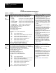
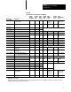
1794 Modules
ControlNet 1794 Flex I/O mapping requires two map-table entries
per adapter.
The ControlNet scheduled transfer mechanism makes it possible to map
the 1794 modules listed in Table 2.H.
Table 2.H
1794
Flex I/O DataT
ransfer Mapping
Module Type
Description
①②
Default
Input
Size
Valid
Input
Size(s)
Default
Output
Size
Valid
Output
Size
1794-OE4/A
1794OE4/A Analog Output Module 1 4
1794-IE4XOE2/A
1794IE4XOE2/A Analog I/O Module 5 15 2
1794-IE8/A
1794IE8/A Analog Input Module 9 19
①
ENPT Default = 4 x NUT
②
ENPT Range = 215000 ms
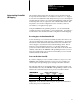
Other ControlNet Processors
ControlNet scheduled peer-to-peer communications between ControlNet
processors require one map-table entry per message. The PLC-5
processor at node 01, the controlling processor, must be included in
each message.
The ControlNet transfer mechanism makes it possible to map the
scheduled peer-to-peer messages listed in Table 2.I.
Table 2.I
PeertoPeer
Communications Mapping
Message Type
Description
①②
Default Input Size Valid Input Sizes
Peer In
Scheduled Peer In
64
1
64
Peer Out to __
Scheduled Peer Out
64 164
①
ENPT Default = 4 x NUT
②
ENPT Range = 215000 ms