
User Manual Owner manual


Chapter 2
Planning to Use Your ControlNet
PLC5 Processor
2-9
Mapping ControlNet Data Transfer
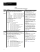
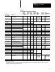
The ControlNet I/O map table can contain up to 64 entries. Each map-
table entry corresponds to one transfer—either input or output—of data
between the ControlNet processor and an I/O rack, an I/O module, or
another ControlNet processor.
Table 2.D
Number
of ControlNet I/O MapT
able Entries Required
DataTransfer
T
ype Number of Entries Required
1771 Discrete I/O Data Transfer
1 per adapter
1771 Nondiscrete I/O Data Transfer 1 or 2 per module
1794 Discrete and Nondiscrete I/O Data Transfer 2 per adapter
ControlNet PLC5 Peertopeer Communication 1 per message
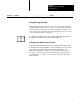
Table 2.E
Files
That Y
ou Configure with the I/O Map for Scheduled I/O Usage
File Description
Status File
Userspecified integer datatable file containing status information about all of the ControlNet network's scheduled I/O
maptable entries. Each entry has a statusfile offset field pointing to three status words associated with the entry.
Data Input File (DIF) Userspecified integer datatable file with a maximum of 1000 words. This space is used for both nondiscrete input data
and peertopeer input over the ControlNet network. Scheduled peertopeer inputs can also use the inputimage file.
Data Output File (DOF) Userspecified integer datatable file with a maximum of 1000 words. This space is used for both nondiscrete output data
and peertopeer output over the ControlNet network. Scheduled peertopeer outputs can also use the outputimage file.
Default Configuration File Userspecified integer datatable file used to store nondiscrete I/O data transfer configuration data when the automatic
mapping feature is used.
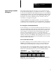
Table 2.F
ControlNet
I/O MapT
able Entry Fields
MapTable Entry Field Description
Node and Slot/Message Numbers
This is the entry's network location, currently defined as node.slot/message. The node value is the ControlNet
network address of the destination device. The slot/message value takes on different meanings with the
different communication options:
• 1771 and 1794 discrete I/O data transferthe slot value does not apply because the mapping granularity is
based on the physical chassis
• 1771 nondiscrete I/O data transfer015, the slot number is always the physical slot location inside the
1771 chassis regardless of addressing mode within the chassis
• 1794 nondiscrete I/O data transfer07, the slot number is always the physical location in the 1794 system
• peertopeer communication116, the message number represents one of sixteen scheduled peer
messages available per processor; and it must be the same for both processors involved
Module/Message Type This allows you to specify the module type or peertopeer message typePeer Out or Peer Inin offline and
online programming. It also determines how the maptable entries are configured for the different modules and
peertopeer messages.
Expected Network Packet Time
(ENPT)
You set this to the maximum time allowed for the network to update the requested data.
Actual Network Packet Time (ANPT) This readonly field displays the actual time it takes for the network to update the requested data.