
User Manual Owner manual


Chapter 1
Installing Your ControlNet PLC5 Processor
1-13
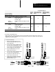
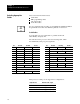
The maximum number of
If your remote I/O link:
Use this
resistor
rating:
physical devices that
you can connect on the
link is:
logical rack numbers
that you can scan on
the link is:
Operates at 230.4K bit/s
Operates at 57.6K or 115.2K bit/s,
and no devices listed below are linked
Scanners 1771SN; 1772SD, SD2;
1775SR, S4A, S4B;
6008SQH1, SQH2
Adapters 1771AS; 1771ASB (Series A Only); 1771DCM
Miscellaneous 1771AF
82W
32 16
Connects to any device listed below:
Scanners 1771SN; 1772SD, SD2;
1775SR, S4A, S4B;
6008SQH1, SQH2
Adapters 1771AS; 1771ASB (Series A Only); 1771DCM
Miscellaneous 1771AF
150W
16 16
Operates at 57.6K or 115.2K bit/s, and you do not require over 16 physical devices
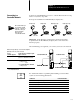
PLC5/40C
Processor
PLC5/20C
Processor
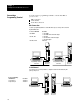
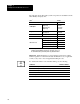
To connect remote I/O cable:
1. Run the 1770CD cable from the processor to
each remote I/O adapter module or processor in
the remote I/O system.
2. Connect the signal conductor with blue insulation
to the 3pin connector terminal labeled 1 on the
processor and to each remote I/O adapter module
(or PLC5 adapter) in the remote I/O system.
3. Connect the shield drain wire to the center
terminal of the 3pin connector.
4. Connect the signal conductor with clear insulation
to the 3pin connector terminal labeled 2.
5. Tie wrap the remote I/O network cable to the
chassis to relieve strain on the cable.
6. Terminate the remote I/O link by connecting an
external terminator resistor between the remote
I/O terminals labeled 1 and 2.
To another I/O
link device
1770CD
Clear
Shield
Blue
82Ω or
150Ω
resistor
Clear
Shield
Blue
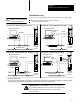
Terminate both ends of a remote I/O link
1770CD
You can install a remote I/O link two ways:
• trunk cable / drop cablefrom the drop cable to the connector screw terminals on the remote I/O connectors of the processor
• daisy chainto the connector screw terminals on the remote I/O connectors of the processor and then to the remote I/O screw
terminals of the next remote I/O device