
User Manual Owner manual


Chapter 1
Installing Your ControlNet PLC5 Processor
1-11
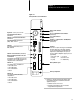
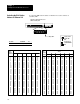
Specify RS-232C, RS-422A, or RS-423 communication for Channel 0 by
setting the switches of assembly SW2.
Front of
Processor
Front of
Processor
Bottom View of PLC5/20C Processor
Switch Assembly SW2
Bottom View of PLC5/40C processor
Switch Assembly SW2
12345678910
12345678910
To Specify:
Set Switches:
To Specify:
12345678910
RS232C
ON ON ON OFF OFF ON ON OFF ON OFF
RS422A
OFF OFF ON OFF OFF OFF OFF OFF ON OFF
RS423
ON ON ON OFF OFF ON OFF OFF ON OFF
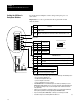
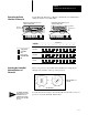
Select your processor’s ControlNet network address by setting the two
10-digit rotary switches on the top of the processor.
00
10
20 30
40
50
60
7080
90
0
1
23
4
5
6
78
9
NET ADDRESS
Network address 01
is shown
You can select from as many as 99 network addresses (from 01 to 99) for a
processor on a ControlNet link. 00 is invalid.
Specifying
the Serial
Interface of Channel 0
Toggle pushed
ON
Toggle pushed
OFF
toward BOTTOM
toward TOP
Selecting the ControlNet
Network Address of
Channel 2
Tip
For optimum throughput,
assign addresses to your
ControlNet nodes in a
sequential order starting
with 01 for the controlling
processor.