
User Manual Owner manual


Chapter 1
Installing Your ControlNet PLC5 Processor
1-7
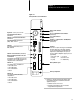
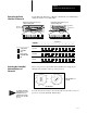
Set the I/O chassis configuration plug as follows:
USING A
POWERSUPPLY
MODULE IN
THE CHASSIS?
1. Locate the chassis configuration plug
(between the two left most slots of
the chassis).
2. Set the I/O chassis configuration plug.
The default setting is N (not using a
powersupply module in the chassis).
NY
N
Y
NY
Set Y when you install a
powersupply module in
the chassis.
Set N when you
use an external
power supply.
Important: You cannot power a single I/O chassis
with both a powersupply module and an external
power supply.
17075
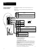
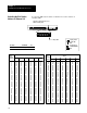
You receive plastic keying bands with each I/O chassis. Insert the keying
bands as follows:
2
4
6
8
10
12
14
16
18
20
22
24
26
28
30
32
34
36
38
40
42
44
46
48
50
52
54
56
I/O Chassis
Backplane
Connector
Keying
Bands
(1771RK)
Use these
numbers
as a guide.
12062
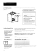
ATTENTION: A module inserted into a wrong slot
could be damaged by improper voltages connected
through the wiring arm. Use keying bands to prevent
damage to the module.
!
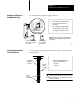
Install a keying band in the leftmost
slot between the following pins:
• 40 and 42
• 54 and 56
Setting
the I/O Chassis
Configuration Plug
Installing Keying Bands
for the Processor