
User Manual Owner manual


Chapter 1
Installing Your ControlNet PLC5 Processor
1-5
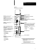
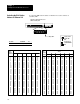
Figure 1.2
PLC5/40C
Processor Front Panel
Battery Status Indicator
(Red)
Processor RUN/FAULT Status Indicator
(Green/Red)
Force Status Indicator
(Amber)
Channel 0 Communication ACTIVE/FAULT
Status Indicator
(Green/Red)
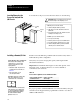
Memory Module Space
Battery Compartment
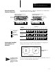
Use this port with ASCII or DF1 fullduplex, half
duplex master, and halfduplex slave protocols.
The port's default configuration supports processor
programming:
Keyswitchselects processor mode
Channel 0
Serial Port25pin Dshell; supports standard EIA
RS232C and RS423; is RS422A compatible
➀
DH+ Programming Terminal Connection
to Channel 1A
8pin miniDIN, parallel with 3pin connectors
of Channel 1A; use only when Channel 1A is
configured for DH+ communications
• one stopbit
• BCC error check
• no handshaking
• DF1 pointtopoint
• 2400 bps
• no parity
Channel 2
ControlNet Redundant Media Ports
BNC; dedicated
➀
Channel 0 is optically coupled (provides high electrical
noise immunity) and can be used with most RS422A
equipment as long as:
• termination resistors are not used
• the distance and transmission rate are reduced to
comply with RS423 requirements
ControlNet Network Access Port
(NAP)RJ45 connector
Channel 1 Status Indicators (Green/Red)
Channel 1A
3 pin; default is DH+; configurable for:
• remote I/O scanner
• remote I/O adapter
• DH+ communication
• unused
Channel 1B
3 pin; default is remote I/O scanner;
configurable for:
• remote I/O scanner
• remote I/O adapter
• DH+ communication
• unused
Channel 2 ControlNet Status Indicators
(Green/Red)
ControlNet I/O Status Indicator
(Green/Red)