ControlNet PLC 5 Programmable Controllers Cat. No.
Important User Information Because of the variety of uses for the products described in this publication, those responsible for the application and use of this control equipment must satisfy themselves that all necessary steps have been taken to assure that each application and use meets all performance and safety requirements, including any applicable laws, regulations, codes, and standards.
Table of Contents Using This Manual . . . . . . . . . . . . . . . . . . . . . . . . . . . . . . . i Introduction . . . . . . . . . . . . . . . . . . . . . . . . . . . . . . . . . . . . . . . . Audience . . . . . . . . . . . . . . . . . . . . . . . . . . . . . . . . . . . . . . . . . . Contents . . . . . . . . . . . . . . . . . . . . . . . . . . . . . . . . . . . . . . . . . . Terminology . . . . . . . . . . . . . . . . . . . . . . . . . . . . . . . . . . . . . . . . Conventions . . . . . . . . . . . . .
ii Table of Contents Configuring Your ControlNet System . . . . . . . . . . . . . . . . . 3 1 Using This Chapter . . . . . . . . . . . . . . . . . . . . . . . . . . . . . . . . . . Matching the Processor Configuration with the ControlNet Configuration . . . . . . . . . . . . . . . . . . . . . . . . . . . . Defining Local Rack Characteristics . . . . . . . . . . . . . . . . . . . . . . . Editing ControlNet Node Information . . . . . . . . . . . . . . . . . . . . . . Editing ControlNet I/O Mapping . . . .
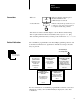
Preface Using This Manual Introduction This manual describes how to install your processor as well as how to plan for, configure, and use the features of a PLC-5/20Ct or PLC-5/40Ct programmable controller that are unique to the ControlNett network. More Audience For detailed information on features that the PLC-5/20C or PLC-5/40C programmable controllers share with the PLC-5/20t and -5/40t processors, see the Enhanced and Ethernet PLC-5 Programmable Controllers User Manual, publication 1785-6.5.12.
Preface Using This Manual Terminology ii Term Description ControlNet network communication architecture that allows the exchange of data between Allen Bradley Company, Inc.
Preface Using this Manual Conventions This icon indicates that the current topic is discussed further in the publication(s) referenced More A series like this Any Menu indicates a keystroke procedure for you to follow to get to the correct screen or to complete a task using software Fx Text that shows what a terminal displays is shown like this: Press a key Text in square brackets indicates an actual key that you press—i.e., [F1] Text describing information that you must provide is italicized—i.e.
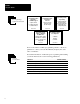
Preface Using This Manual PLC 5 Programming Software Documentation PLC 5 Programming Software Programming PLC 5 Programming Software Supplement ConttrolNet Support PLC 5 Programming Software Instruction Set Reference Using the software to configure and monitor a ControlNet network Instruction execution, parameters, status bits and examples Creating/managing files, saving/restoring files, importing/exporting files creating/editing SFCs, creating/editing ladder 6200 6.4.20 6200 6.4.11 6200 6.4.
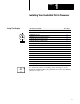
Chapter 1 Installing Your ControlNet PLC 5 Processor Using This Chapter More If you want to read about: Go to page: Completing the preliminary setup 1 2 Checking the contents of the processor package 1 2 Handling the processor 1 3 Identifying the processor channels/connectors 1 4 Setting the I/O chassis backplane switches 1 6 Setting the I/O chassis configuration plug 1 7 Installing keying bands for the processor 1 7 Installing and disposing of the processor battery 1 8 Selecting the
Chapter 1 Installing Your ControlNet PLC 5 Processor Before You Begin Before installing your ControlNet PLC-5 processor: 1. Complete the following: determine the proper environment configure the proper grounding route the conductors properly For detailed information on completing these tasks, see the Enhanced and Ethernet PLC-5 Programmable Controllers User Manual, publication 1785-6.5.12. More 2.
Chapter 1 Installing Your ControlNet PLC 5 Processor Handling the Processor Your processor is shipped in a static-shielded container to guard against electrostatic damage. Electrostatic discharge can damage integrated circuits or semiconductors in the processor if you touch backplane connector pins. It can also damage the module when you set configuration plugs or switches inside the module. Avoid electrostatic damage by observing the following precautions.
Chapter 1 Installing Your ControlNet PLC 5 Processor Identifying ControlNet PLC 5 Processor Components Figure 1.1 and Figure 1.2 show the front panels of the ControlNet PLC-5 processors. Figure 1.
Chapter 1 Installing Your ControlNet PLC 5 Processor Figure 1.
Chapter 1 Installing Your ControlNet PLC 5 Processor Setting the I/O Chassis Backplane Switches Set the I/O chassis backplane switches using a ball-point pen to set each switch. Important: Do not use a pencil because the tip can break off and short the switch. Switch Last State 1 O 1 N O F F ON Outputs of this I/O chassis remain in their last state when a hardware failure occurs.➀ OFF Outputs of this I/O chassis are turned off when a hardware failure occurs.
Chapter 1 Installing Your ControlNet PLC 5 Processor Setting the I/O Chassis Configuration Plug Set the I/O chassis configuration plug as follows: Y N USING A POWER SUPPLY MODULE IN THE CHASSIS? Y N Set Y when you install a power supply module in the chassis. Installing Keying Bands for the Processor 1. Locate the chassis configuration plug (between the two left most slots of the chassis). 2. Set the I/O chassis configuration plug.
Chapter 1 Installing Your ControlNet PLC 5 Processor Installing and Disposing of the Processor Battery More The 1770-XYC battery ships with the processor and requires special handling. For more detailed information on installing and disposing of the battery, see the Allen-Bradley Guidelines for Lithium Battery Handling and Disposal, publication AG-5.4. ATTENTION: To maintain CSA certification for hazardous areas, do not substitute any other battery for the 1770-XYC.
Chapter 1 Installing Your ControlNet PLC 5 Processor Replacing the Battery Tip You can insert or remove the battery without powering down the processor. If you do not want to lose your program, make sure that the processor is powered when replacing the battery. Replace the lithium battery every year or when the BATT status indicator is red.
Chapter 1 Installing Your ControlNet PLC 5 Processor Selecting the DH+ Station Address of Channel 1A To select the DH+ station address of Channel 1A, set the switches of assembly SW1.
Chapter 1 Installing Your ControlNet PLC 5 Processor Specifying the Serial Interface of Channel 0 Specify RS-232C, RS-422A, or RS-423 communication for Channel 0 by setting the switches of assembly SW2.
Chapter 1 Installing Your ControlNet PLC 5 Processor Inserting/Removing the Processor into/from the I/O Chassis To insert/remove the processor into/from the chassis, do the following: ATTENTION: Make certain that power to the chassis is off before inserting or removing the processor. ! To insert a processor into the chassis: Locking Bar Ejector Tab 1. Lift the locking bar and the ejector tab. 2. Slide the processor into the left most slot of the I/O chassis. 3.
Chapter 1 Installing Your ControlNet PLC 5 Processor The maximum number of Use this resistor rating: If your remote I/O link: physical devices that you can connect on the link is: logical rack numbers that you can scan on the link is: Operates at 230.4K bit/s Operates at 57.6K or 115.
Chapter 1 Installing Your ControlNet PLC 5 Processor Installing a DH+ Link Use 1770-CD cable to connect the processor to a DH+ link. Follow these guidelines while installing DH+ communication links: do not exceed these cable lengths: - trunk-cable length—3,048 m (approximately 10,000 cable-ft) - drop-cable length—30.4 m (approximately 100 cable-ft) do not connect more than 64 stations on a single DH+ link Use the 3 pin connector on the processor to connect a DH+ link.
Chapter 1 Installing Your ControlNet PLC 5 Processor Connecting to a ControlNet Network Connect a ControlNet PLC-5 processor to a ControlNet network via a tap with a 1-m (39.4-in) drop cable. Four taps are available from Allen-Bradley Company, Inc.: Straight T tap Tip We recommend that you use a tap with a straight connector 1786 TPS or 1786 TPYS when you attach a ControlNet PLC 5 processor to a ControlNet network.
Chapter 1 Installing Your ControlNet PLC 5 Processor Connecting a Programming Terminal You can connect a programming terminal to a ControlNet PLC-5 processor via a: DH+ connection serial channel ControlNet connection DH+ Connection To attach a programming terminal to a ControlNet PLC 5 processor using a DH+ connection: If you use this card to access a DH+ link: Use cable: 1784 PCMK G 1784 PCM6 G 1784 PCM5 with a 1784 CP7 adapter 1784 KT, KT2 G 1784 CP6 G 1784 CP6 with a 1784 CP7 adapter G 1784 CP8
Chapter 1 Installing Your ControlNet PLC 5 Processor ControlNet Connection ! ATTENTION: Do not connect the same communication card to both the NAP and a tap on the ControlNet network.
Chapter 1 Installing Your ControlNet PLC 5 Processor Selecting Appropriate Cables More This section lists information about: serial cables DH+ programming cables remote I/O cables ControlNet cables For more information about cables, see the Enhanced and Ethernet PLC-5 Programmable Controllers User Manual, publication 1785-6.5.12. Serial Cables You can make your own serial cables or purchase them from Allen-Bradley Company, Inc.
Chapter 1 Installing Your ControlNet PLC 5 Processor Important: Follow these guidelines: When Channel 0 is configured for RS-422A compatibility, do not use terminating resistors anywhere on the link. When Channel 0 is configured for RS-422A (compatible) and RS-423, do not go beyond 61 m (approximately 200 ft). This distance restriction is independent of the transmission rate.
Chapter 1 Installing Your ControlNet PLC 5 Processor The following ControlNet cable system components are available from the Allen-Bradley Company, Inc.: Item① Cat. No. ControlNet Coax Tool Kit 1786 CTK Coax Tap Kit Right angle T tap Straight T tap Right angle Y tap Straight Y tap 1786 TPR 1786 TPS 1786 TPYR 1786 TPYS Repeaters High voltage ac & dc Low voltage dc 1786 RPT 1786 RPTD RG 6 Quad Shield Cable Standard PVC CM CL2 1786 RG6 ControlNet Network Access Cable 3.
Chapter 2 Planning to Use Your ControlNet PLC 5 Processor Using This Chapter Understanding ControlNet I/O If you want to read about: Go to page: Understanding ControlNet I/O 2 1 Understanding ControlNet I/O mapping 2 7 Using the ControlNet PLC 5 processor in a ControlNet I/O system 2 13 Converting from a remote I/O system to a ControlNet I/O system 2 15 The ControlNet system is designed to: provide high-speed, repeatable, deterministic I/O transmission allow control and message information to
Chapter 2 Planning to Use Your ControlNet PLC 5 Processor Data Update Scheduled Data Transfer Data Table Files Logic Scan Private Memory Buffers Housekeeping Scheduled Data Transfers A similar method is used for all scheduled data-transfer operations. Program Scan The following scheduled data-transfer operations are supported by the PLC-5/20C and -5/40C processors on a ControlNet network: Table 2.
Chapter 2 Planning to Use Your ControlNet PLC 5 Processor Unscheduled Data Transfer Operations on a ControlNet Network The ControlNet network allows you to use unscheduled messaging when deterministic delivery is not required.
Chapter 2 Planning to Use Your ControlNet PLC 5 Processor Table 2.B ControlNet Unscheduled Data Transfer Operations Operation Description Features Non discrete Perform ladder initiated unscheduled non discrete I/O data transfers on a ControlNet network by using ControlNet I/O Transfer (CIO) instructions.
Chapter 2 Planning to Use Your ControlNet PLC 5 Processor Operation ① Description Features Because connections are opened and closed as needed, more can exist in a program as long as no more than this number are active at one time. Using I/O Forcing Operations ControlNet I/O forcing occurs in the same way as remote I/O forcing in the PLC-5/20 and -5/40 processors. The processor performs the forcing and transmits the forced data to the output- and input-image tables.
Chapter 2 Planning to Use Your ControlNet PLC 5 Processor Immediate Data Transfer Data Update ControlNet Data Transfer ÇÇ ÉÄÉ ÉÉ Data Table Files Logic Scan Private Memory Buffers Housekeeping ÉÉ Ä ÉÉ ÇÄ ÉÉ Ç ÉÉ Ä Ç ÉÉ Ç Ç Program Scan = NUI = Scheduled Data Transfer = Unscheduled Data Transfer Table 2.
Chapter 2 Planning to Use Your ControlNet PLC 5 Processor Understanding ControlNet I/O Mapping All scheduled data transfers must be mapped on a ControlNet network. You specify where I/O data is to be read from or written to—i.e., mapped. You do this and establish the relationship between processors, I/O adapters, and data-table file addresses by creating and maintaining an I/O map table. An I/O map-table entry is required for each scheduled data transfer.
Chapter 2 Planning to Use Your ControlNet PLC 5 Processor Remote I/O The following table shows the default number of input and output words reserved by the 6200 PLC-5 Programming Software for the different sizes and addressing modes of non-ControlNet remote I/O if you first configure non-ControlNet remote I/O on your processor: Addressing Mode 2 Slot 1 Slot 1/2 Slot 4 Slots 2 4 8 Number of Words Reserved 8 Slots 12 Slots 16 Slots 4 6 8 8 12 16 16 24 32 The 6200 PLC-5 Programming Software reserves non-C
Chapter 2 Planning to Use Your ControlNet PLC 5 Processor Mapping ControlNet Data Transfer The ControlNet I/O map table can contain up to 64 entries. Each maptable entry corresponds to one transfer—either input or output—of data between the ControlNet processor and an I/O rack, an I/O module, or another ControlNet processor. Table 2.
Chapter 2 Planning to Use Your ControlNet PLC 5 Processor Map Table Entry Field Description Input File and Size This is the offset in the input file where the data is to be stored and the number of words to be received from the input device. For discrete I/O data transfer, the offset is into the input image table; for non discrete I/O data transfer or peer to peer communication with another ControlNet processor, the offset is into the Data Input File entered on the ControlNet configuration screen.
Chapter 2 Planning to Use Your ControlNet PLC 5 Processor Table 2.G 1771 Non discrete I/O Data Transfer Mapping Default Default Entries Input per Module Size Valid Input Size(s) Default Output Size Valid Output Sizes Default Config.
Chapter 2 Planning to Use Your ControlNet PLC 5 Processor The types of modules that may be accommodated by the processor’s scheduled non-discrete I/O data-transfer mechanism are typically those modules that require a one-time configuration and then continuously read or write. To communicate with the modules listed in Table 2.G as well as with other 1771 analog modules, you can also include explicit CIO instructions in your ladder-logic program. See pages 4-4 and C-1 for more information.
Chapter 2 Planning to Use Your ControlNet PLC 5 Processor To communicate between any ControlNet PLC-5 processors on the ControlNet network, you can include explicit MSG instructions in your ladder-logic program. See pages 4-2 and C-1 for more information. Using the ControlNet PLC 5 Processor in a ControlNet I/O System There can be only one PLC-5/20C or -5/40C processor updating I/O adapters on a ControlNet network.
Chapter 2 Planning to Use Your ControlNet PLC 5 Processor Personal Computer or Other Serial Device and ControlView or 6200 Series Programming Software Personal Computer with 1784 KTCx Card and ControlView or 6200 Series Programming Software Personal Computer with 1784 KTCx or 1784 KTC Card and ControlView or 6200 Series Programming Software PLC 5/40C Controlling Processor Serial Connection 1770 KFC Interface ControlNet Network 1794 ACN Flex I/O Adapter 1771 ACN Adapter Example of a ControlNet Netwo
Chapter 2 Planning to Use Your ControlNet PLC 5 Processor Converting from a Non ControlNet Remote I/O System to a ControlNet I/O System Program files① for this process: When you download archived files to a PLC-5/20C or -5/40C processor, the 6200 PLC-5 Programming Software ignores Channel 2 configuration information from anything other than a ControlNet-processor program because Channel 2 is reserved for ControlNet communication on the PLC-5/20C and -5/40C processors.
Chapter 2 Planning to Use Your ControlNet PLC 5 Processor Program files① for this process: I/O ① Archived from a: • PLC 5/20E • PLC 5/60L PLC 5/40E • PLC 5/40E • PLC 5/80E PLC 5/80E • PLC5/40L On channel: Can be run on a PLC 5/20C or 5/40C channel: 2 1A or 1B performed by remote I/O you must make these changes manually by reprogramming⑤ 2 performed by the ControlNet network you must make these changes manually by reprogramming③④⑤ If they fit and are: These include processor files, data table fi
Chapter 3 Configuring Your ControlNet System Using This Chapter If you want to read about: Go to page: Matching the processor configuration with the ControlNet configuration 3 2 Defining local rack characteristics 3 3 Editing the ControlNet node information 3 4 Editing ControlNet I/O mapping 3 6 Editing ControlNet 1794 I/O module action 3 10 ControlNet Configuration Edit Screens in the 6200 Programming Software Fx = Function Key Channel Overview ControlNet Node Information (Edit) F5 See
Chapter 3 Configuring Your ControlNet System Matching the Processor Configuration with the ControlNet Configuration Follow the steps on the left to go to the ControlNet Node Information (Monitor) screen. If the ControlNet information in the processor does not match that on the current ControlNet link, the software redisplays the Channel Overview screen with a new prompt and set of function keys.
Chapter 3 Configuring Your ControlNet System Defining Local Rack Characteristics If you are programming offline, configuring Channel 2 for the first time, and entering an edit screen for the first time—or if you follow the steps on the left—the software prompts you to select the number of slots in the local chassis and your addressing mode.
Chapter 3 Configuring Your ControlNet System Editing ControlNet Node Information Follow the steps on the left to go to the ControlNet Node Information (Edit) screen. Important: Only one user on a network can enter a processor’s ControlNet Node Information (Edit) screen at one time.
Chapter 3 Configuring Your ControlNet System If you want to: Do this: view the percent of scheduled bandwidth used in the worst case a percent that changes depending on the ControlNet configuration See the Scheduled Bandwidth Usage field specify the redundancy characteristic for the ControlNet channel 1. Move the cursor to the Media Redundancy Usage field specify the node with the highest network address that can use scheduled time on the ControlNet link 2.
Chapter 3 Configuring Your ControlNet System Editing ControlNet I/O Mapping Follow the steps on the left to go to the ControlNet I/O Mapping (Edit) screen. Important: 6200 Main Menu Online Program Only one user on a network can enter a processor’s ControlNet I/O Mapping (Edit) screen at one time.
Chapter 3 Configuring Your ControlNet System If you want to: Do this: specify the NUT 1. Move the cursor to the Network Update Time (ms) field 2. Type a number between 2 and 100 3.
Chapter 3 Configuring Your ControlNet System If you want to: Do this: view the offset into the status file that con tains the status information for a module or message (determined by the software) See the Status Offset field for the item manually enter the file for storing the I/O configuration needed for a module e.g., a 1771 IFE or 1794 ACN 1. Move the cursor to the module's Config File field 2.
Chapter 3 Configuring Your ControlNet System If you want to: Do this: insert an entry or range of entries into the list 1. Move the cursor to the node where you want to add a module or message 2. Press [F7]—Insert to List 3. Type the slot or message number (slot/message or node.slot/message) for a single new entry or range (slot/message slot/message or node.slot/message slot/message) for multiple new entries 4. Press [Enter] delete a module or message 1.
Chapter 3 Configuring Your ControlNet System Editing ControlNet 1794 I/O Module Action Follow the steps on the left to the ControlNet I/O Action (Edit) screen. 6200 Main Menu Online Program Offline Program or F1 Important: Only one user on a network can enter a processor’s ControlNet 1794 I/O Module Action screen at one time.
Chapter 3 Configuring Your ControlNet System If you want to: Do this: change a module's idle action i.e., the action that it takes when it becomes idle 1. Move the cursor to the module's Idle Action field 2. Press [F10]—Toggle Entry to toggle between: • Reset to change all outputs to zero • Hold Last to maintain all current output values • Safe to change all outputs to user specified fail-safe values change a module's fault action 1.
Chapter 4 Programming Your ControlNet System Using This Chapter If you want to read about using: Go to page: ControlNet message instructions 4 2 ControlNet I/O transfer instructions 4 4 ControlNet immediate data input and output instructions 4 6 Using Selectable Timed Interrupts (STIs) in a program on a ControlNet network 4 7 4-1
Chapter 4 Programming Your ControlNet System Using ControlNet Message Instructions Monitor File You can use the existing MG data type to send two message commands over the ControlNet system within the local ControlNet link—PLC-5 TYPED WRITE and PLC-5 TYPED READ. Follow the steps on the left to go to the Instruction Entry for Message Block screen.
Chapter 4 Programming Your ControlNet System Follow the steps on the left to go to the Data Monitor for Message Control Block screen.
Chapter 4 Programming Your ControlNet System Using the ControlNet I/O Transfer Instruction 6200 Main Menu You can use the ControlNet I/O Transfer (CIO) instruction and the ControlNet Transfer (CT) data type to make ControlNet I/O transfers within the local ControlNet link. Follow the steps on the left to go to the Instruction Entry for ControlNet I/O Transfer Block screen.
Chapter 4 Programming Your ControlNet System Follow the steps on the left to go to the Data Monitor for ControlNet I/O Transfer Block screen.
Chapter 4 Programming Your ControlNet System Using ControlNet Immediate Data Input and Output Instructions Follow the steps on the left to add IDI and IDO instructions to your program. 6200 Main Menu Online Program or You can use two instructions for immediate data input and output on a ControlNet network—Immediate Data Input (IDI) and Immediate Data Output (IDO).
Chapter 4 Programming Your ControlNet System More For more detailed information on writing ladder programs, see the PLC-5 Programming Software Instruction Set Reference, publication 6200-6.4.11, and PLC-5 Programming Software Programming, publication 6200-6.4.7. For information on programming ControlNet I/O transfers using Immediate Input (INN) and Immediate Output (IOT) instructions, see the PLC-5 Programming Software Instruction Set Reference, publication 6200-6.4.11.
Chapter 5 Monitoring and Troubleshooting Your ControlNet System Using This Chapter If you want to read about: See page: Using the general status indicators 5 2 Using the ControlNet status indicators 5 3 Monitoring the ControlNet configuration and status screens 5 5 5-1
Chapter 5 Monitoring and Troubleshooting Your ControlNet System Using the General Status Indicators Indicator BATT BATT The general status indicators inform you of the general operational state of the processor.
Chapter 5 Monitoring and Troubleshooting Your ControlNet System Using the ControlNet Status Indicators Indicator I/O A B I/O The ControlNet status indicators inform you of the operational state of the ControlNet network.
Chapter 5 Monitoring and Troubleshooting Your ControlNet System Indicator State➀ Probable Cause Off No power Steady Red Faulted unit If fault persists, contact your Allen Bradley Company, Inc.
Chapter 5 Monitoring and Troubleshooting Your ControlNet System Using the 6200 Programming Software to Monitor ControlNet Configuration and Status This section shows you how to use the ControlNet configuration monitor and status screens found in the 6200 PLC-5 Programming Software, release 5.1 or later.
Chapter 5 Monitoring and Troubleshooting Your ControlNet System Using the ControlNet Node Information (Monitor) Screen Follow the steps on the left to go to the ControlNet Node Information (Monitor) screen.
Chapter 5 Monitoring and Troubleshooting Your ControlNet System Using the ControlNet I/O Mapping (Monitor) Screen Follow the steps on the left to go to the ControlNet I/O Mapping (Monitor) screen.
Chapter 5 Monitoring and Troubleshooting Your ControlNet System Using the ControlNet View Times Screen Follow the steps on the left to go to the ControlNet View Times screen.
Chapter 5 Monitoring and Troubleshooting Your ControlNet System Using the ControlNet Map Entries Status Screen Follow the steps on the left to go to the ControlNet Map Entries Status screen.
Chapter 5 Monitoring and Troubleshooting Your ControlNet System If you want to: Do this: clear the inhibit bit so that the processor 1. Move the cursor to the Inhibit field for that entry will attempt to establish a connection with 2. Type a 0 the module or message 3. Press [Enter] 5-10 set the reset bit so that the processor will set the output module or message's Run/Program command to Program mode 1. Move the cursor to the Reset field for that entry 2. Type a 1 3.
Chapter 5 Monitoring and Troubleshooting Your ControlNet System Using the ControlNet I/O Action (Monitor) Screen Follow the steps on the left to go to the ControlNet I/O Action (Monitor) screen.
Chapter 5 Monitoring and Troubleshooting Your ControlNet System Using the ControlNet Channel 2 Status Screen Follow the steps on the left to go to the ControlNet Channel 2 Status screen.
Chapter 5 Monitoring and Troubleshooting Your ControlNet System This status field: Word; Bits:① Displays:② when the display of the counters stops changing the counters continue to run in the background; current values are continuously updated when COUNTERS LOCKED is not displayed COUNTERS LOCKED the media redundancy characteristic for the ControlNet channel A/B, A Only, or B Only media usage Frames transmitted good transmitted aborted received good 6; 15 08 5; 07 00 5; 15 08 15 08 number of good f
Chapter 5 Monitoring and Troubleshooting Your ControlNet System Using the ControlNet WHO ACTIVE Active Node Identification Screen Important: Keep the following in mind: ControlNet WHO screens are available only when your programming device is communicating through a 1784-KTC card, 1784-KTCx card, or 1770-KFC interface on the ControlNet network. When you view the WHO screens while your ControlNet system is operating, you affect the performance of unscheduled I/O operations.
Chapter 5 Monitoring and Troubleshooting Your ControlNet System This field: Displays: Net Channel Status Line the status of channel A and channel B • Cable Good = channel is usable • Cable WARN = channel is experiencing problems but still usable • Cable FAULTED = channel is not usable • Cable Inactive = channel unused (in non redundant network) 5-15
Chapter 5 Monitoring and Troubleshooting Your ControlNet System Using the ControlNet WHO ACTIVE Active Node Status Screen Important: Keep the following in mind: ControlNet WHO screens are available only when your programming device is communicating through a 1784-KTC card, 1784-KTCx card, or 1770-KFC interface on the ControlNet network. When you view the WHO screens while your ControlNet system is operating, you affect the performance of unscheduled I/O operations.
Chapter 5 Monitoring and Troubleshooting Your ControlNet System Using the ControlNet WHO ACTIVE Channel Status Screen Important: Keep the following in mind: ControlNet WHO screens are available only when your programming device is communicating through a 1784-KTC card, 1784-KTCx card, or 1770-KFC interface on the ControlNet network. When you view the WHO screens while your ControlNet system is operating, you affect the performance of unscheduled I/O operations.
Appendix A Processor Specifications Heat Dissipation 54 BTU/hr Environmental Conditions Operating Temperature: Storage Temperature: Relative Humidity: Shock and Vibration 0 to 60° C (32 140° F) 40 to 85° C ( 40 to 185° F) 5 to 95% (without condensation) Vibration Testing (operating and non operating): 1 g @ 10 to 500 Hz 0.012 inches peak to peak displacement Shock: Operating . . . . . . 30 g peak acceleration for 11±1 ms duration Non operating . . . .
Appendix A Processor Specifications PLC 5/20C PLC 5/40C Maximum User Memory Words 16K 48K① Any Mix 512 2048 512 in and 512 out 2048 in and 2048 out Maximum Total I/O Complimentary 0.
Appendix B Processor Status File Processor status data is stored in data-file 2.
Appendix B Processor Status File S:3 10 B-2 This word of the status file: Stores: S:3 to S:6 Active Node table for channel 1A Word Bits DH+ Station # 3 0 15 00 17 4 0 15 20 37 5 0 15 40 57 6 0 15 60 77 S:7 Global status bits: • low 8 bits rack fault bits for racks 0 7 • high 8 bits rack queue full bits for racks 0 7 S:8 Last program scan (in ms) S:9 Maximum program scan (in ms) S:10 Minor fault (word 1) Bit Description 0 battery is missing or low (replace in 1 2 days) 1 DH+ table has changed
Appendix B Processor Status File S:11 S:12 This word of the status file: Stores: S:11 Major fault Bit Description 0 corrupted program file (codes 10 19) 1 corrupted address in ladder file (codes 10 29) 2 programming error (codes 30 49) 3 SFC fault (codes 71 79) 4 error while assembling program (code 70) 5 start up protection fault 6 peripheral device fault 7 jumped to fault routine (codes 0 9) 8 watchdog faulted 9 system configured wrong (codes 80 89) 10 recoverable hardware error 11 MCP does not exis
Appendix B Processor Status File S:12 S:16 B-4 This word of the status file: Stores: S:12 (continued) Fault codes Code Description 70 duplicate labels 71 SFC subchart is already executing 72 tried to stop an SFC that is not running 73 maximum number of SFC subcharts exceeded 74 SFC file error 75 SFC contains too many active steps 77 SFC references a step, transition, subchart, or SC file that is missing, empty, or too small 78 SFC could not continue after power loss 79 error in downloading an SFC to
Appendix B Processor Status File S:17 S:27 This word of the status file: Stores: S:17 Minor fault (word 2) Bit Description 0 BT queue full to remote I/O 1 queue full channel 1A 2 queue full channel 1B 3 queue full channel 2A 4 queue full channel 2B 5 no modem on serial port 6 remote I/O rack in local rack table; or, remote I/O rack is greater than the image size 7 plug firmware revision does not match processor firmware revision 8 ASCII instruction error 9 duplicate network address 10 DF1 master poll
Appendix B Processor Status File S:28 S:61 B-6 This word of the status file: Stores: S:28 Program watchdog setpoint S:29 Fault routine file S:30 STI setpoint S:31 STI file number S:32 Global status bits: • low 8 bits rack fault bits for racks 10 17 (octal) • high 8 bits rack queue full bits for racks 10 17 S:33 Rack control bits: • low 8 bits I/O rack inhibit bits for racks 10 17 • high 8 bits I/O rack reset bits for racks 10 17 S:34 Global status bits: • low 8 bits rack fault bits for ra
Appendix B Processor Status File S:62 S:127 This word of the status file: Stores: S:62 Extended I/O channel maximum block transfer scan (in ms) S:63 Protected processor data table protection file number S:64 Number of remote block transfer command blocks being used by channel pair 1A/1B S:76 Number of slots in processor resident local rack 0 1 2 3 4 Illegal 4 slots 12 slots 8 slots 16 slots S:77 Communication time slice for communication housekeeping functions (in ms) S:78 MCP I/O update di
Appendix C ControlNet Instruction Set ControlNet I/O Transfer Instruction Instruction CIO CNET I/O TRANSFER Control block CT21:50 Description ControlNet I/O Transfer CT If the input conditions go from false to true, the data is transferred according to the instruction parameters you set when you enter the ControlNet I/O transfer instruction. The Control Block (CT21:50) contains status and instruction parameters.
Appendix C ControlNet Instruction Set Immediate Data I/O Instructions Instruction Description IDI IMMEDIATE DATA INPUT Data file offset Length 232 If the input conditions are true, an immediate data input is initiated that updates the destination file from the private buffers before the next normal input image update. The Data file offset (232) is where the data is stored.
Appendix D ControlNet I/O Map Entry Status Words and Error Messages I/O Map Entry Status Words The ControlNet status file is an integer data-table file that you specify and configure with the I/O map for scheduled-I/O usage. It containing status information about all of the ControlNet network’s scheduled I/O connections. Each I/O map-table entry has a status-file offset field pointing to three status words associated with the connection.
Appendix D ControlNet I/O Map Entry Status Words and Error Messages Error Messages The following is a list of ControlNet error codes, messages, possible causes, and possible corrective actions: Decimal Code Hex.
Appendix D ControlNet I/O Map Entry Status Words and Error Messages Decimal Code Hex.
Appendix D ControlNet I/O Map Entry Status Words and Error Messages Decimal Code Hex.
Allen Bradley Publication Problem Report If you find a problem with our documentation, please complete and return this form. Pub. Name Cat. No. Check Problem(s) Type: Pub. No. Pub. Date Part No.
PLEASE FASTEN HERE (DO NOT STAPLE) PLEASE FOLD HERE NO POSTAGE NECESSARY IF MAILED IN THE UNITED STATES BUSINESS REPLY MAIL FIRST-CLASS MAIL PERMIT NO.
Index Numbers 1770 CD, 1 14, 1 19 1770 KFC Communication Interface, 2 13 1770 KFC Communication Interface, 1 17 1771 Generic, 2 11 1771 N Series Analog Modules, 2 11 1771 AF, 1 13 1771 AS, 1 13 1784 KL, 1 19 1784 KL/B, 1 19 1784 KTC Communication Card, 2 13 1784 CP, 1 16, 1 19 1784 CP11, 1 16 1784 CP13, 1 16, 1 19 1784 CP5, 1 19 1784 CP6, 1 16, 1 19 1771 DCM, 1 13 1784 CP7, 1 16, 1 19 1771 IE, IF, and IFE Analog Input Modules, 2 11 1784 KT, KT2, 1 16, 1 19 1784 KTC Communication Card, 1 17 1771 IL I
I–2 Index 1794 ACN ControlNet Flex I/O Adapter, 2 13 1794 IE4XOE2/A Analog I/O Modules, 2 12 1794 IE8/A Analog Input Modules, 2 12 1794 OE4/A Analog Output Modules, 2 12 6008 SQH1, SQH2, 1 13 A automatic I/O mapping, 2 7 avoiding electrostatic damage, 1 3 B battery, specifications, A 1 battery compartment, 1 4, 1 5 location of on PLC 5/20C, 1 4 on PLC 5/40C, 1 5 battery life, 1 9 battery status indicator, 1 4, 1 5 C cables, remote I/O, 1 12 cabling, 1 19 certification, A 1 Channel 0, 1 4, 1 5 Channel
Index scheduled discrete I/O data transfer, 2 1 scheduled operations discrete I/O data transfer, 2 2 non discrete I/O data transfer, 2 2 peer to peer communication, 2 2 understanding, 2 1 unscheduled data transfer operations, 2 3 unscheduled non discrete I/O data transfer, 2 3 unscheduled operations ControlNet I/O Transfer (CIO) instruction, description, C 1 ControlNet I/O Transfer (CIO) instructions description, 2 4 features, 2 4 I/O transfer instructions, programming, 4 4 immediate data I/O instructions,
I–4 Index copying node information to a new address, 3 5 defining local rack characteristics, 3 3 deleting a module or message, 3 9 deleting a node from the node list, 3 5 deleting all modules and messages, 3 9 deleting all nodes from the node list, 3 5 editing 1794 I/O module action, 3 10 editing ControlNet I/O mapping, 3 6 editing node information, 3 4 editing the ControlNet node information configuration, 3 4 entering the length of cable between repeaters, 3 4 entering the number of coax repeaters, 3 4
Index Data Output File description, 2 9, 2 10 specifying, 3 6 Default Configuration File description, 2 9 specifying, 3 6 defining local rack characteristics, 3 3 DH+, trunk cable/drop cable connection, 1 14 DH+ programming terminal connection (PTC), 1 4, 1 5 I–5 I/O status, 2 9 input, 2 10 input image, 2 1, 2 9, 2 10 output, 2 10 output image, 2 1, 2 10 processor status, B 1 force status indicator, 1 4, 1 5 frame, definition of, ii front panel PLC 5/20C processor, 1 4 PLC 5/40C processor, 1 5 Diagnosti
I–6 Index manually entering the amount of information to be stored in the I/O configuration file for a module, 3 8 manually entering the destination file for information received from a module or message, 3 7 manually entering the file for storing the I/O configuration needed for a module, 3 8 manually entering the source file for information sent to a module or in a message, 3 7 map table creating, 2 7 entries, 2 7 maximum number of entries, 2 9 map table entry configuration file, 2 10 module/message typ
Index disposing of the battery, 1 9 handling the processor, 1 3 identifying the components of the processor, 1 4 installing a DH+ link, 1 14 installing a remote I/O link, 1 12 installing keying bands for the processor, 1 7 installing the battery, 1 8 installing the processor in the chassis, 1 12 locating additional information, 1 1 preparing for, 1 2 removing the processor from the chassis, 1 12 selecting cables ControlNet cables, 1 19 DH+ programming, 1 19 remote I/O, 1 19 serial, 1 18 selecting the Contr
I–8 Index number of map table entries required, 2 10 nonredundant media, 1 15 NUI. See Network Update Interval NUT.
Index changing I/O status files, 2 16 downloading archived files, 2 15 I/O performed on Channel 2 of PLC 5/40L processor, 2 16 messaging and I/O performed on Channels 1A and 1B, 2 15 messaging and I/O performed on Channels 2A and 2B of PLC 5/40B processor, 2 15 using automatic mapping, 2 7 replacing the processor battery, 1 9 S scheduled data transfer operations, 2 1 descriptions of, 2 2 scheduled discrete I/O data transfer, process, 2 1 scheduled peer to peer communication description, 2 2 number of map
I–10 Index using ControlNet Immediate Data I/O instructions, 4 6 using the ControlNet WHO ACTIVE Active Node Identification screen, 5 14 using ControlNet Message (MSG) instructions, 4 2 using the ControlNet WHO ACTIVE Active Node Status screen, 5 16 using the ControlNet Channel 2 Status screen, 5 12 using the ControlNet WHO ACTIVE Channel Status screen, 5 17 using the ControlNet I/O Action (Monitor) screen, 5 11 using the ControlNet I/O Mapping (Monitor) screen, 5 7 using the ControlNet Map Entries
Allen Bradley, a Rockwell Automation Business, has been helping its customers improve productivity and quality for more than 90 years. We design, manufacture, and support a broad range of control and automation products worldwide. They include logic processors, power and motion control devices, man machine interfaces, sensors, and a variety of software. Rockwell is one of the world's leading technology companies. Worldwide representation.