
Installation Instructions User guide

Publication 1785-IN062A-EN-P - May 2005
12 Enhanced PLC-5 Programmable Controllers
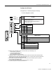
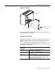
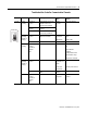
2. Set the power supply configuration jumper and set the keying bands as
shown below
.
For more information, see the Universal I/O Chassis installation instructions,
publication number 1771-IN075.
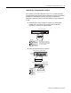
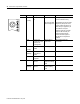
Install the Power Supply
Install a power supply according to one of the following corresponding
installation instructions:
TIP
Configuring an I/O rack for a local controller is different than
configuring a remote I/O rack using a 1771-ASB module. For
more information about configuring a remote I/O rack using
a 1771-ASB module, see the following:
• Remote I/O Adapter Module User Manual, publication
number, 1771-6.5.83
• Enhanced and Ethernet PLC-5 Programmable
Controllers User Manual, publication number
1785-UM012
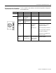
YN
Keying
Bands
Are you using a power
supply module in
the chassis?
between
- 40 & 42
- 54 & 56
PLC-5/20
Controller
YN
2
4
6
8
10
12
14
16
18
20
22
24
26
28
30
32
34
36
38
40
42
44
46
48
50
52
54
56
12345678
O
N
O
F
F
Install this Power Supply: According to this Publication:
1771-P4S
1771-P6S
1771-P4S1
1771-P6S1
Power Supply Modules Installation Instructions, pub.
no. 1771-2.135
1771-P7 Power Supply Module Installation Instructions, pub.
no. 1771-IN056