Installation Instructions Enhanced PLC-5 Programmable Controllers Cat. Nos. 1785-L11B, -L20B, -L30B, -L40B, -L40L, -L60B, -L60L, -L80B Purpose of This Document This document describes how to install and troubleshoot your Enhanced PLC-5® programmable controller. For more information, see the documents listed on the following page or contact your local Rockwell Automation representative.
Enhanced PLC-5 Programmable Controllers Important User Information Solid state equipment has operational characteristics differing from those of electromechanical equipment. Safety Guidelines for the Application, Installation and Maintenance of Solid State Controls (Publication SGI-1.1 available from your local Rockwell Automation sales office or online at http://www.ab.com/manuals/gi) describes some important differences between solid state equipment and hard-wired electromechanical devices.
Enhanced PLC-5 Programmable Controllers 3 North American Hazardous Location Approval The following information applies when operating this equipment in hazardous locations: Informations sur l’utilisation de cet équipement en environnements dangereux : Products marked “CL I, DIV 2, GP A, B, C, D” are suitable for use in Class I Division 2 Groups A, B, C, D, Hazardous Locations and nonhazardous locations only.
Enhanced PLC-5 Programmable Controllers Environment and Enclosure ATTENTION Publication 1785-IN062A-EN-P - May 2005 • This equipment is intended for use in a Pollution Degree 2 industrial environment, in overvoltage Category II applications (as defined in IEC publication 60664-1), at altitudes up to 2000 meters without derating. • This equipment is considered Group 1, Class A industrial equipment according to IEC/CISPR Publication 11.
Enhanced PLC-5 Programmable Controllers How to Obtain a User Manual 5 The related user manual contains detailed information about configuring, programming, and using an Enhanced PLC-5 controller. To obtain a copy of the Enhanced and Ethernet PLC-5 Programmable Controllers User Manual, publication number 1785-UM012, you can either: • view or download an electronic version from the internet at www.rockwellautomation.
Enhanced PLC-5 Programmable Controllers Enhanced PLC-5 Programmable Controller Overview The following illustrations indicate the controller’s front panel components.
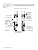
Enhanced PLC-5 Programmable Controllers 7 PLC-5/30 Controller Front Panel battery indicator (lights red when the battery is low) processor RUN/FAULT indicator (green when running; red when faulted) keyswitch; selects controller mode channel 1A status indicator (lights green and red) 8-pin mini-DIN, DH+ programming terminal connection parallel to channel 1A channel 1A communication port; its default configuration is DH+ channel 1B communication port; its default configuration is remote I/O scanner force
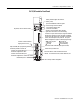
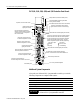
Enhanced PLC-5 Programmable Controllers PLC-5/40, -5/46, -5/60, -5/80, and -5/86 Controller Front Panels battery indicator (red when the battery is low) processor RUN/FAULT indicator (green when running; red when faulted) keyswitch; selects controller mode channel 2A status indicator (lights green and red) 8-pin mini-DIN, DH+ programming terminal connection parallel to channel 2A when channel 2A is configured for DH+ communications force indicator (amber when I/O forces are enabled) channel 0 communi
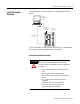
Enhanced PLC-5 Programmable Controllers Install the System Hardware 9 This illustration shows a basic Enhanced PLC-5 programmable controller system. PC with Programming Software PLC-5/20 Programmable Controller Internal Power Supply Data Highway Plus For more information, see the Enhanced and Ethernet PLC-5 Programmable Controllers User Manual, publication number 1785-UM012.
Enhanced PLC-5 Programmable Controllers Prepare to Install the Controller Installing the controller is one part of setting up the hardware in your system. WARNING If you either insert or remove any module while backplane power is on, OR connect or disconnect any cable with power applied to this module or the device on the other end of the cable, an electrical arc can occur. This could cause an explosion in hazardous location installations.
Enhanced PLC-5 Programmable Controllers 11 Configure the I/O Chassis Configure the I/O chassis by doing the following: 1. Set the backplance switches. Pressed in at top ON (closed) Pressed in at bottom OFF (open) Switch 1 on O1 N O F F off 2 3 Always Off Last State 1 Outputs of this I/O chassis remain in their last state when a hardware failure occurs. 1 Outputs of this I/O chassis are turned off when a hardware failure occurs.
Enhanced PLC-5 Programmable Controllers 2. Set the power supply configuration jumper and set the keying bands as shown below. Are you using a power supply module in the chassis? PLC-5/20 Controller Y N Keying Bands YN O 1 N O F F 2 3 4 2 4 6 8 10 12 14 16 18 20 22 24 26 28 30 32 34 36 38 40 42 44 46 48 50 52 54 56 5 6 between - 40 & 42 - 54 & 56 7 8 TIP Configuring an I/O rack for a local controller is different than configuring a remote I/O rack using a 1771-ASB module.
Enhanced PLC-5 Programmable Controllers 13 Install the PLC-5 Programmable Controller The controller is a modular component of the 1771 I/O system requiring a properly installed system chassis. Refer to publication 1771-IN075 for detailed information on acceptable chassis along with proper installation and grounding requirements. Limit the maximum adjacent slot power dissipation to 10W. 1. Define the DH+ Station Address of Channel 1A by setting switch assembly SW-1 on the back of the controller.
Enhanced PLC-5 Programmable Controllers 3. Depending on your controller catalog number, install the battery as shown below: Locking Bar Ejector Tab Battery Connector is Attached to a Wiring Harness Battery Connector is mounted inside the Battery Compartment Battery Cover Battery Card Guides Battery 1785-L11 and -L20 Programmable Controllers WARNING 1785-L30, -L40, -L60 and -L80 Programmable Controllers When you connect or disconnect the battery, an electrical arc can occur.
Enhanced PLC-5 Programmable Controllers 15 Install the I/O Modules Locking Bar Install each I/O module and connect the wiring arm. Card Guides 20618-M For more information, see the installation instructions or user manual for the particular module you are installing. Apply Power to the System Apply power to the system. Check the LED display on the controller. If your system is operating properly, the PROC LED should be steady red and the message “Processor RAM is faulted.
Enhanced PLC-5 Programmable Controllers To monitor your system as you configure and run it, check the controller LED display for the following indicators: This LED: Lights when: COMM you establish serial communication (CH 0) BATT no battery is installed or the battery voltage is low REM I/O you establish Remote I/O communication ADAPT the controller is in adapter mode FORCE forces are present in your ladder program Connect the Personal Computer to the PLC-5 Programmable Controller For more
Enhanced PLC-5 Programmable Controllers Troubleshoot the Controller 17 Use the controller’s status indicators with the following tables for diagnostics and troubleshooting.
Enhanced PLC-5 Programmable Controllers Indicator Color Description Probable Cause Recommended Action PROC Red Fault with memory loss New controller Use programming software to clear and initialize memory Processor has failed internal diagnostics Install battery (to preserve failure diagnostics), then power down, reseat controller and power up; then reload your program. If you are unable to reload your program, replace the controller.
Enhanced PLC-5 Programmable Controllers 19 Troubleshoot the Controller Communication Channels A A Indicator Color Channel Mode Description Probable Cause Recommended Action A or B Green (steady) Remote I/O Scanner Active Remote I/O link, all adapter modules are present and not faulted Normal operation No action required Remote I/O Adapter Communicating with scanner DH+ Controller is transmitting or receiving on DH+ link Remote I/O Scanner At least one adapter is faulted or has failed
Enhanced PLC-5 Programmable Controllers Controller Specifications General Specifications Backplane Current PLC-5/11, -5/20, -5/30: 2.3A @ 5Vdc PLC-5/40, -5/40L, -5/46, -5/60, -5/60L, -5/80, -5/86: 3.
Enhanced PLC-5 Programmable Controllers 21 Specifications (continued) Hardware Addressing Communication 2-slot • Any mix of 8-pt modules • 16-pt modules must be I/O pairs • No 32-pt modules 1-slot • Any mix of 8- or 16-pt modules • 32-pt modules must be I/O pairs 1/2-slot—Any mix of 8-,16-, or 32-pt modules • Serial • DH+ (trunk line: 3048 cable-m (10,000 cable-ft) drop line: 30.
Enhanced PLC-5 Programmable Controllers Battery Type Enhanced PLC-5 programmable controllers use 1770-XYC batteries that contain 0.65 grams of lithium. Average Battery Lifetime Specifications Worst-case battery life estimates In this controller: At this temperature: Power off 100% Power off 50% Battery duration after the LED lights1 PLC-5/11, -5/20 60°C 256 days 1.4 years 11.5 days 25°C 2 years 4 years 47 days 60°C 84 days 150 days 5 days 25°C 1 year 1.
Enhanced PLC-5 Programmable Controllers 23 Memory and Channel Specifications This table lists memory and channel specifications of each Enhanced and extended-local PLC-5 programmable contoller. Cat. No. Maximum Total I/O Maximum Channels User Memory (words) Maximum Number of I/O Chassis Power Backplane Dissipation, Current ControlNet Maximum Load Total Extended Remote -Local 1785-L11B 8K 512 any mix or 384 in + 384 out (complement) 1 DH+/remote I/O 5 0 4 0 12W 2.
Rockwell Automation Support Rockwell Automation provides technical information on the web to assist you in using our products. At http://support.rockwellautomation.com, you can find technical manuals, a knowledge base of FAQs, technical and application notes, sample code and links to software service packs, and a MySupport feature that you can customize to make the best use of these tools.