
User guide
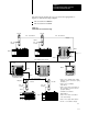

Communicating through the 1785KA5
Communication Adapter Module
Chapter 3
3-15
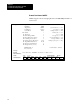
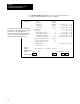
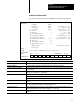
Remote Read from a 485CIF
If you select a remote read from a 485CIF, the following screen appears:
Display Area:
Message:
Prompt:
Data/Cmd Entry:
Status:
Type:
Read/Write:
Target Device:
Channel:F10
Target Node:F1
Remote Bridge Link ID:F2
Remote Bridge Node Address:F3
Local Bridge Node Address:F4
Local/Remote:
Control Block:
Destination/Source File Address:F5
Target OffsetF6
Message Length in Elements:F7
Message Timeout (seconds):F8
ERROR CODE:
Error Code Desc:
0 control bit address: N10 : 0/8
Peer-to-Peer
READ
485CIF
0
3
3
0
4
Remote
N10 : 0
N7 : 0
20
5
10
ignore if timed out:
continuous run:
error:
message done:
message transmitting
message enabled
to be retried:
awaiting execution:
waiting for queue space:
TO
CO
ER
DN
ST
EN
NR
EW
WQ
0
0
0
0
0
0
0
0
0
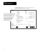
Press a function key: <ENTER> to save and exit, or <ESC> to abort
offline no forces INSTR INSERT File 009
Main Functions:
F1 F2 F3 F4 F5 F6 F7 F8 F9 F10
TARGET
NODE
REMOTE
LINK ID
REMOTE
ADDRESS
LOCAL
ADDRESS
FILE
ADDRESS
TARGET
OFFSET
MESSAGE
LIMIT
MESSAGE
TIMEOUT
TOGGLE
BIT CHANNEL
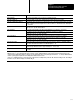
Function Key Description
[F1] Target Node Specifies the node number of processor that is receiving the message. Valid range is 0 - 254 decimal.
[F2] Remote LINK_ID Specifies the LINK_ID of the remote network where the remote target processor resides.
[F3] Remote Bridge Node Address Use when the remote target device is a SLC fixed, 5/01, 5/02, or any other noninternet device. Valid range
is 0 - 15 decimal.
[F4] Local Address Specifies the node address of the bridge residing on the local network that provides the link to the remote
target processor. Valid range is 0 - 254 decimal.
[F5] File Address For a Read (Destination) this is the address in the initiating processor that is to receive data.
For a Write (Source) this is the address in the initiating processor that is to send data.
Valid file types are S, B, T, C, R, N, I, O, M0, M1.
[F6] Target Offset For a Read or Write this is the word offset value in the common interface file (byte offset for nonSLC
device).
[F7] Message Length Defines the length of the message in elements. One word elements are limited to a maximum length of 1
-112. Three word elements are limited to a maximum length of 1 - 37.
[F8] Message Timeout Defines the length of the message timer in seconds. A timeout of 0 seconds means that there is no timer
and the message will wait forever for a reply. Valid range is 0 - 255 seconds.
[F10] Channel Identifies the physical channel used for the message communication. Available channels are (RS232, 0) or
(DH485, 1).