
User guide

Communicating through the 1785KA5
Communication Adapter Module
Chapter 3
3-5
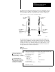
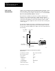
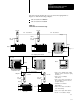
The figure below demonstrates internet router mode communication from a
PLC-5 processor (on DH+) to another PLC-5 (on a remote DH+ network)
across the DH485. The auto route enable switch, switch 2 of SW-2 (see
page 2-2) is set to on (1) for both 1785-KA5 modules.
DH485LINK_ID=2
DH+
LINK_ID=1
DH+
LINK_ID=3
DH+LINK_ID1,
station10
DH+LINK_ID3,
station15
DH+LINK_ID3,
station14
DH+LINK_ID1,
station11
PLC5 PLC5
1785-KA5 1785-KA5
19235
DH485 LINK_ID 2,
station 12
DH485 LINK_ID 2,
station 13
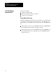
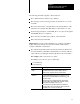
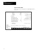
The message instruction below (as shown in Allen-Bradley 6200 Series
software) shows the PLC-5 on the left writing 64 words from its data file
N20:0 to data file N21:0 of the remote PLC-5 on the right. The 1785-KA5
modules (in router mode) determine which device in the internet to route
the message, so if the internet contains multiple 1785-KA5 modules, the
message still reaches its intended destination.
Figure 3.2
Message
instruction
Communication command: PLC-5 typed write
PLC-5 data table address: N20:0
size in elements: 64
Local/Remote: Remote
Remote station: 15
LINK_ID: 3
Remote link type: DATA HIGHWAY
Local node address: 11
Destination data table address: N21:0
Block size = 11 words
In this message transfer process:
the message is first sent to the
local node, which is the 1785KA5
module (DH+ LINK_ID = 1, STATION 11)
the 1785KA5 determines the
location of the remote station in the
internet and reroutes it to the proper
destination, which is the PLC5
(DH+LINK_ID = 3, STATION 15)
MESSAGE INSTRUCTION DATA ENTRY FOR CONTROL BLOCK N10:0