
User guide

Installing the 1785KA5
Communication Adapter Module
Chapter 2
2-13
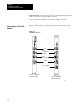
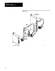
Important: If the 1785-KA5 module is attached at either end of the
DH485 network trunk cable, install a wire jumper between pins 4 and 6 of
the 6-pin mating connector supplied with the module. This is the
termination resistor for the network.
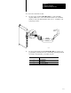
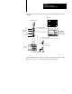
5. If you are connecting a 1785-KA5P/B panel-mount module, you need
to connect the external power supply:
Important: To meet the Low Voltage Directive regulations within the
European Union or EEA Regions, you must use a Class 2 Safety Extra-low
Voltage power supply.
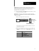
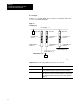
a. Wire a power supply cable as shown below:
5V dc
supply @
3 Amps
4pin Phoenixstyle connector
supplied with 1785KA5P/B module
(CHASSIS GROUND) Green/Yellow
+5V dc Red
(connect to power
connector on the
1785KA5P/B module)
(no connection)
0V dc (dc GND) Black
14 AWG standard colorcoded wire
4
3
2
1
The earth ground or chassis ground wire should be color-coded
green with a yellow stripe.
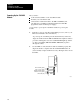
b. Wire the cable using the 4-pin connector you received with your
module and connect the cable to the EXT PWR connector on the
module.
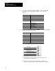
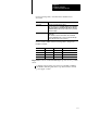
Pin Signal
1 no connection
2 +5V dc @ 2.0 amps (red)
3 0Vdc (dc GND) black
4 (Chassis Ground) green/yellow