
User guide

Installing the 1785KA5
Communication Adapter Module
Chapter 2
2-9
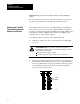
3. Slide the 1785-KA5 module into one of the slots in the 1771 I/O rack.
Make sure the module is seated properly. Snap down the latch on the
top of the module to secure proper placement in the rack (You can
change the position of the keying bands if subsequent system design
requires the insertion of a different type of module in this slot).
Now you are ready to connect the module (see page 2-10.)
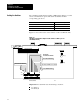
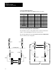
The rear edge of the 1785-KA5 panel-mount version contains a mounting
bracket that lets you install the module. If you are using a
dropline/trunkline configuration, mount the 1785-KA5 panel-mount
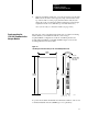
module within 10-100 feet of the DH+ trunkline. Figure 2.2 shows the
mounting dimensions for the module.
Figure 2.2
1785KA5
panelmount module (Cat. No. 1785KA5P/B) dimensions
305mm
(12.0")
149mm
(5.87")
39mm
(1.53")
288mm
(11.35")
hole size
accommodates
up to 1/4 - 20
size screw
19194
To protect the module from harmful environmental conditions, enclose it in
a standard industrial enclosure (NEMA type 12 or equivalent.)
Panelmounting the
1785KA5 Communication
Adapter Module