
User guide

Installing the 1785KA5
Communication Adapter Module
Chapter 2
2-2
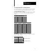
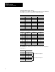
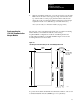
The 1785-KA5 module has three banks of DIP switches that let you select
various communication options. The switch assemblies and their
corresponding options are:
To set the Use switch assembly
DH485 station address and baud rate SW1
DH+ station address and the auto route enable option SW2
DH485 and DH+ channel LINK_IDs SW3
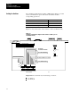
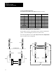
Figure 2.1 shows the location of the switches on the 1785-KA5 module.
Figure 2.1
1785KA5
communication adapter module switch assemblies (cat. no.
1785KA5/B shown)
B7
B6
B5
B4
B3
B2
B1
B0
B3
B2
B1
B0
B3
B2
B1
B0
B4
B3
B2
B1
B0
SW - 1 SW - 2
SW - 3
ON
OFF
ON
(1)
switch assemblies
19191
DH485 BAUD RA
TE
DH485 ST
A
TION ADDRESS
DH+ STA
TION ADDRESS
DH485 CHANNEL DH+ IP LINK ID
DH+ CHANNEL LINK ID
RESERVED
AUTO ROUTE ENABLE
OFF
(0)
LEGEND
Important: The 1785-KA5 uses the following convention:
on = binary 1
off = binary 0
Setting the Switches