Data Highway Plus/DH485 Communication Adapter Module (Cat. No.
Important User Information Because of the variety of uses for the products described in this publication, those responsible for the application and use of this control equipment must satisfy themselves that all necessary steps have been taken to assure that each application and use meets all performance and safety requirements, including any applicable laws, regulations, codes and standards. The illustrations, charts, sample programs and layout examples shown in this guide are intended solely for example.
Summary of Changes Summary of Changes Summary of Changes This publication contains new information not included in the last release. New Information European Union Directive Compliance Information on the European Union Directive is located on pages 2-1 and A-1. Auto Routing Feature Detailed information on using the Auto Routing Feature is located on pages 2-4 and 2-5. Power Supply Requirements Detailed information on power supply requirements for the European Union Directive is located on page 2-13.
Table of Contents Using this Manual . . . . . . . . . . . . . . . . . . . . . . . . . . . . . . . i Purpose of this Manual . . . . . . . . . . . . . . . . . . . . . . . . . . . . . . . . Who Should Read this Manual . . . . . . . . . . . . . . . . . . . . . . . . . . Frequently Used Terms . . . . . . . . . . . . . . . . . . . . . . . . . . . . . . . Related Publications . . . . . . . . . . . . . . . . . . . . . . . . . . . . . . . . . . Updated Information . . . . . . . . . . . . . . . . . . . . . . . . .
Preface Using this Manual Purpose of this Manual This manual describes the 1785-KA5 Data Highway Plus/DH485 communication adapter module.
Preface Using this Manual Related Publications These Allen-Bradley publications contain related information: Publicaton Publication Number SLC 500 Overview brochure 1746 1.1 Bulletin 1746/47 SLC 500 Modular Hardware Style Programmable Controllers I/O manual 1747 804 Hand Held Terminal user's manual 1747 809 Programming Terminals (Cat. Nos. 1784 T45, T47, T50) product data 1784 2.1 DH+ LAN product data 1785 2.6 PLC 5 Family Processor product data 1785 2.
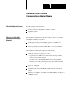
Chapter 1 Overview of the 1785 KA5 Communication Adapter Module What this Chapter Contains Read this chapter for information on: what the 1785-KA5 communication adapter module is what DH+ and DH485 networks are compatible products What is the 1785 KA5 Communication Adapter Module? The 1785-KA5 communication adapter module lets devices on the Data Highway Plus (DH+) network communicate with devices on the RS-485 Data Highway (DH485) network for: uploading/downloading of SLC 500 programs from a DH+ devi
Chapter 1 Overview of the 1785 KA5 Communication Adapter Module DH+ and DH485 Networks This section describes the DH+ and DH485 networks. For more information on these networks, see the DH/DH+/DH485 Protocol and Command Set reference manual (publication 1770-6.5.16). DH+ Networks DH+ is a baseband local area network (LAN) that allows peer-to-peer communication among a maximum of 64 nodes. Each node has a unique station address between 0–63 decimal and 0–77 octal.
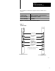
Chapter 1 Overview of the 1785 KA5 Communication Adapter Module The 1785-KA5 communication adapter module is available in two versions: Use this version If your application is 1771 I/O rack mount (Cat. No. 1785-KA5/B) primarily DH+ with multiple 1771 I/O racks and SLC 500 subnetworks within close proximity stand alone panel mount (Cat. No. 1785 KA5P/A) primarily a SLC (DH485) environment with no 1771 I/O racks in close proximity Figure 1.1 shows the module’s hardware features: Figure 1.
Chapter 1 Overview of the 1785 KA5 Communication Adapter Module The DH485 Network This section describes the DH485 network. For more information on this network, see the DH/DH+/DH485 Protocol and Command Set reference manual (publication 1770-6.5.16). DH485 is a low cost, peer-to-peer programming and data acquisition link for a variety of Allen-Bradley products, such as the SLC 500 family of programmable controllers.
Chapter 1 Overview of the 1785 KA5 Communication Adapter Module Compatible Products You can use the following Allen-Bradley products with the 1785-KA5 module: This product Has this Cat. No.
Chapter 2 Installing the 1785 KA5 Communication Adapter Module What this Chapter Contains This chapter explains how to install the 1785-KA5 module in a 1771 I/O rack or in a stand-alone panel mount setup.
Chapter 2 Installing the 1785 KA5 Communication Adapter Module Setting the Switches The 1785-KA5 module has three banks of DIP switches that let you select various communication options. The switch assemblies and their corresponding options are: To set the Use switch assembly DH485 station address and baud rate SW 1 DH+ station address and the auto route enable option SW 2 DH485 and DH+ channel LINK_IDs SW 3 Figure 2.1 shows the location of the switches on the 1785-KA5 module. Figure 2.
Chapter 2 Installing the 1785 KA5 Communication Adapter Module SW 1: DH485 Station Address and DH485 Baud Rate Use switch assembly SW-1 to select the DH485 station address and baud rate for the 1785-KA5 module. The following sections show you how. Setting the DH485 Station Address Set switches 1-5 of SW-1 to the DH485 station address for the 1785-KA5. Valid addresses are 0-31 decimal or 0-37 octal.
Chapter 2 Installing the 1785 KA5 Communication Adapter Module Setting the DH485 Baud Rate Set switches 6-8 of SW-1 to the DH485 baud rate as follows: To set this baud rate Set switch 6 to Set switch 7 to Set switch 8 to 300 0 0 0 600 0 0 1 1200 0 1 0 2400 0 1 1 4800 1 0 0 9600 1 0 1 19200 1 1 0 RESERVED 1 1 1 SW 2: Auto Routing and DH+ Station Address The module has an auto routing feature that broadcasts an information packet over the Data Highway network every 30 seco
Chapter 2 Installing the 1785 KA5 Communication Adapter Module If you are not using one of these two network configurations, do not use the auto routing feature.
Chapter 2 Installing the 1785 KA5 Communication Adapter Module Setting the DH+ Station Address Set switches 3-8 of SW-2 to the DH+ station address for the 1785-KA5.
Chapter 2 Installing the 1785 KA5 Communication Adapter Module SW 3: DH485 Channel LINK_ID and DH+ Channel LINK_ID The 1785-KA5 module has two LINK_ID addresses: one for its DH485 side and one for its DH+ side. See the following table to set switches 1-8 of SW-3. Important: Do not use a LINK_ID of 0 (zero). This address is reserved. If you have more than one 1785-KA5 module on a single physical network, the LINK_IDs for the two modules must be the same.
Chapter 2 Installing the 1785 KA5 Communication Adapter Module Important: Each physical network link must have a unique LINK_ID address. The next section shows you how to mount the module in a 1771 I/O rack. See page 2-9 for instructions on mounting the stand-alone version. Mounting the 1785 KA5 Communication Adapter Module in an I/O Rack The 1785-KA5 mounts in any slot of an Allen-Bradley 1771 bulletin I/O rack, except slot zero.
Chapter 2 Installing the 1785 KA5 Communication Adapter Module 3. Slide the 1785-KA5 module into one of the slots in the 1771 I/O rack. Make sure the module is seated properly. Snap down the latch on the top of the module to secure proper placement in the rack (You can change the position of the keying bands if subsequent system design requires the insertion of a different type of module in this slot). Now you are ready to connect the module (see page 2-10.
Chapter 2 Installing the 1785 KA5 Communication Adapter Module Important: Make sure the enclosure leaves a 6 inch (minimum) clearance at the top and bottom of the module for air flow. After you mount the module, you are ready to make connections. Connecting the 1785 KA5 Module Figure 2.3 shows the ports on the front panel of the 1785-KA5 module: Figure 2.3 1785 KA5 connectors DH+ DH+ Programming Terminal AUX (for programmer) DH485 Power Supply Cat. No. 1785 KA5/A rack mount module Cat. No.
Chapter 2 Installing the 1785 KA5 Communication Adapter Module To connect the 1785-KA5 module: 1. Use the 3-pin port labeled Data Hwy Plus to connect the DH+ dropline (100 ft. max.) or the daisy-chained cable to the 1785-KA5 module. Connect the Allen-Bradley cable (cat. no. 1770-CD) to the 3-pin plug as shown: 1770 CD Cable Blue (2) Shield (SH) Clear (1) 20224 2.
Chapter 2 Installing the 1785 KA5 Communication Adapter Module 3. 4. Use the 8-pin modular port labeled AUX to connect the SLC 500 programmer. Use an Allen-Bradley cable (cat. no. 1747-C10 series A): Pin Signal 1 data (A) 2 -data (B) 3 (not used) 4 24v enable (internally connected to ground pin 7) 5 TXEN (from HHT) 6 earth ground (chassis) 7 signal ground 8 +24V dc @ 105 ma Use the 6-pin terminal block labeled DH485 to connect to the DH485 dropline.
Chapter 2 Installing the 1785 KA5 Communication Adapter Module Important: If the 1785-KA5 module is attached at either end of the DH485 network trunk cable, install a wire jumper between pins 4 and 6 of the 6-pin mating connector supplied with the module. This is the termination resistor for the network. 5.
Chapter 2 Installing the 1785 KA5 Communication Adapter Module The following figure shows how typical connections are made on the DH485 link.
Chapter 2 Installing the 1785 KA5 Communication Adapter Module The figure below shows a typical system connection using the 1785-KA5 module: PLC-5/15 1785-KA5 module DH+ Data Highway Plus DH+ Remote Terminal T70 Terminal (with 1784 KT, KTX or KTXD) AUX DH485 DH485 daisy chain 1747-AIC Link coupler SLC 500 controller 1747-C11 Cable 19197 Connect DH485 stations at any point along the length of the cable using a link coupler (cat. no. 1747-AIC) and daisy-chain connections.
Chapter 2 Installing the 1785 KA5 Communication Adapter Module Powering Up the 1785 KA5 Module After you have: set the switch assemblies on the 1785-KA5 module mounted your 1785-KA5 module connected the 1785-KA5 module to the DH+ and DH485 (and, optionally, the 1784-T50 programming terminal, the SLC 500 programmer and the external power supply) you are ready to power up the 1785-KA5 module. To power up the module: 1.
Chapter 2 Installing the 1785 KA5 Communication Adapter Module Use the following table to determine if the installation was successful: If the installation was Then successful -only the green LEDs flash on and off. -the DIP switches are read. All DIP switches are read at this time only. Changes you make after this time are ignored. Important: Always power down the module before you change DIP switch settings.
Chapter 3 Communicating through the 1785 KA5 Communication Adapter Module What this Chapter Contains This chapter includes information on: network addressing how the 1785-KA5 module operates as a router how the 1785-KA5 module operates as a gateway PLC-5 to SLC communication controlling the flow of data Internet Protocol Addressing Each station on the internet must have a unique Internet Protocol (IP) address to help a packet reach its intended receiver.
Chapter 3 Communicating through the 1785 KA5 Communication Adapter Module For example: In Figure 3.1, the DH+ LINK_IDs for all three 1785-KA5 modules must be set to 1 (the DH+ LINK_ID.) Figure 3.
Chapter 3 Communicating through the 1785 KA5 Communication Adapter Module DH+/DH485 STATION Address The DH+ and DH485 address is the low level physical address that identifies a device on a single physical network. Each physical device must have a unique STATION address on that link. You set the STATION address using the switches on the interface module. Valid physical addresses are 0-77 octal for the DH+ network and 0-31 decimal for the DH485 network.
Chapter 3 Communicating through the 1785 KA5 Communication Adapter Module 1785 KA5 Router Communication This section explains: router mode addressing how the 1785-KA5 operates as a router Router Mode Addressing A DH+ device wishing to send an internet packet to a DH485 device must set the internet destination address (LINK_ID, STATION) to the: LINK_ID of the DH485 network STATION address to the DH485 device How the 1785 KA5 Module Operates as a Router The 1785-KA5 module operates as a router when attach
Chapter 3 Communicating through the 1785 KA5 Communication Adapter Module The figure below demonstrates internet router mode communication from a PLC-5 processor (on DH+) to another PLC-5 (on a remote DH+ network) across the DH485. The auto route enable switch, switch 2 of SW-2 (see page 2-2) is set to on (1) for both 1785-KA5 modules.
Chapter 3 Communicating through the 1785 KA5 Communication Adapter Module 1785 KA5 Gateway Communication This section explains: gateway mode addressing how the 1785-KA5 operates as a gateway “single-hop” mode packets Gateway Mode Addressing All DH+ and DH485 destination and source addresses are contained in the lower address byte, leaving the upper byte free for “sub-addressing.
Chapter 3 Communicating through the 1785 KA5 Communication Adapter Module How the 1785 KA5 Module Operates as a Gateway The 1785-KA5 module operates as a gateway when attached DH485 stations do not fully implement IP. It converts IP packets to DH485 local packets and sends them to their DH485 destination stations. Important: SLC 5/01, SLC 5/02 and fixed controllers do not support IP.
Chapter 3 Communicating through the 1785 KA5 Communication Adapter Module PLC 5 to SLC Communication A PLC-5 can communicate with a SLC 500, SLC 5/01, SLC 5/02, or SLC 5/03 using a PLC-5 ladder rung message instruction. These SLC devices do not provide a message instruction, but will respond to UNSOLICITED READ and UNSOLICITED WRITE commands. Read and write commands are addressed to the SLC’s data file 9 (also referred to as its common interface file, or CIF.
Chapter 3 Communicating through the 1785 KA5 Communication Adapter Module The following information applies to this transaction: The command must be a PLC-2-type command. The message is a remote message because the destination is not on the local link. The remote station is the octal equivalent of the decimal address of the destination (for example, SLC 5/02 address = 10 decimal = 12 octal.) In the message instruction, set the LINK_ID to zero (0) even though the actual LINK_ID does not equal zero.
Chapter 3 Communicating through the 1785 KA5 Communication Adapter Module Table 3.
Chapter 3 Communicating through the 1785 KA5 Communication Adapter Module The next sections describe two types of remote messaging. Refer to Figure 3.3 with the following examples: remote read from a 500CPU remote read from a 485CIF Figure 3.3 Connections for a remote message.
Chapter 3 Communicating through the 1785 KA5 Communication Adapter Module Remote Read from a 500CPU DH485 supports remote messaging. Below is the data entry screen for a remote read.
Chapter 3 Communicating through the 1785 KA5 Communication Adapter Module Function Key Description [F1] Target Node Specifies the node number of processor that is receiving the message. [F2] Remote LINK_ID1 Specifies the LINK_ID of the remote network where the remote target processor resides. [F3] Remote Bridge Node Address2 Use when the remote target device is a SLC fixed, 5/01, 5/02, or any other non internet device.
Chapter 3 Communicating through the 1785 KA5 Communication Adapter Module The monitor display screen allows you to monitor the status of the message instruction while the processor is running. Display Area: In this screen, the 5/03 processor reads 5 elements (words) from Target node 3 of Remote Bridge LINK_ID 2, starting at word N7:50. If 20 seconds elapse without a reply, F10 F1 error bit N10:012 will be set, indicating that the instruction has timed out.
Chapter 3 Communicating through the 1785 KA5 Communication Adapter Module Remote Read from a 485CIF If you select a remote read from a 485CIF, the following screen appears: Display Area: F10 F1 F2 F3 F4 F5 F6 F7 F8 Peer-to-Peer Type: READ Read/Write: 485CIF Target Device: Remote Local/Remote: N10 : 0 Control Block: 0 Channel: 3 Target Node: 3 Remote Bridge Link ID: 0 Remote Bridge Node Address: 4 Local Bridge Node Address: N7 : 0 Destination/Source File Address: 20 Target Offset 5 Message Length in Elem
Chapter 3 Communicating through the 1785 KA5 Communication Adapter Module The monitor display screen allows you to monitor the status of the message instruction while the processor is running: Display Area: In this screen, the 5/03 processor reads 5 elements (words) from Target node 3 or Remote Bridge LINK_ID 3, starting at byte offset 20 of its PLC 3 compatibility file. This is a byte offset because the device at node 3 is a PLC-5/40. The 5 elements are placed in the integer file starting at word N7:0.
Chapter 3 Communicating through the 1785 KA5 Communication Adapter Module Controlling the Flow of Data The data transfer rate is much higher for DH+ links (57.6 KB) than for DH485 links (19.2 KB), so DH+ devices must control the flow of data to DH485 devices. For example, a DH+ device can send packets to the 1785-KA5 adapter three times faster than the gateway can send the packets out to their DH485 destinations.
$SSHQGL[ 6SHFLILFDWLRQV &RPPXQLFDWLRQ 5DWHV 'DWD +LJKZD\ 3OXV '+ ELWV SHU VHFRQG 56 'DWD +LJKZD\ '+ VZLWFK VHOHFWDEOH IURP WR ELWV SHU VHFRQG )XQFWLRQ LQWHUIDFH D SURJUDPPDEOH 56 FRPSDWLEOH GHYLFH ZLWK DQ $OOHQ %UDGOH\ '+ QHWZRUN 0RXQWLQJ /RFDWLRQ .$ % VLQJOH VORW LQ EXOOHWLQ , 2 UDFN .
Index Numbers 1785-KA5 Communication Adapter module, using more than one, 2 7 1785-KA5 communication adapter module defined, 1 1 illustrated, 1 3 1785-KA5 gateway module specifications, A 1 using more than one, 3 1 1785-KA5 panel mount module, when to use, 1 3 1785-KA5 rack mount module, when to use, 1 3 C compatible products, 1 5 connecting the module, 2 10 D data flow control, 3 17 DH+ network, 1 2 setting the channel LINK_ID, 2 7 setting the station address, 2 4 DH485 network setting the baud rate, 2
Allen Bradley, a Rockwell Automation Business, has been helping its customers improve productivity and quality for more than 90 years. We design, manufacture and support a broad range of automation products worldwide. They include logic processors, power and motion control devices, operator interfaces, sensors and a variety of software. Rockwell is one of the worlds leading technology companies. Worldwide representation.