
Configuration Manual Owner's manual

Publication 1784-UM003A-EN-P – June 2003
Wiring Diagrams 427
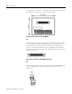
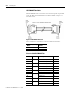
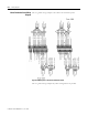
Sync Cable
Up to four (4) 1784-PM02AE cards may be installed in a single computer
provided there are enough PCI Bus slots available. A sync cable is required to
keep the cards synchronized. This is a ribbon cable with four connectors that
fit to the cards.
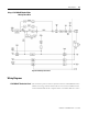
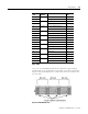
Figure B.8 1784-PMCSY4 Cable
8 Pair 8 OK 1 8
42 IN_COM, Axis 0 42
9 Pair 9 IN_COM, Axis 0 9
43 IN_COM, Axis 1 43
10 Pair 10 +CH A Feedback Input Axis 1 10
44 - CH A Feedback Input Axis 1 44
11 Pair 11 +CH B Feedback Input Axis 1 11
45 -CH B Feedback Input Axis 1 45
12 Pair 12 +CH Z Feedback Input Axis 1 12
46 -CH Z Feedback Input Axis 1 46
13 Pair 13 +OUT, Axis 1 13
47 -OUT, Axis 1 47
14 Pair 14 DRVFLT, Axis 1 14
48 HOME, Axis 1 48
15 Pair 15 REG1, Axis 1 15
49 REG2, Axis 1 49
16 Pair 16 +ENABLE, Axis 1 16
50 -ENABLE, Axis 1 50
17 Pair 17 OK 2 17
51 IN_COM, Axis 1 51
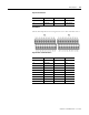
Pin
(PX)
Pin Pair
Number
Pin Description Pin
(PY)