
Configuration Manual Owner's manual

Publication 1784-UM003A-EN-P – June 2003
426 Wiring Diagrams
1784-PM02AE-TP0x Cable
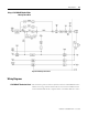
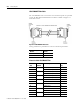
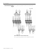
The 1784-PM02AE card is connected to the termination panel via a premade
34 pair, 28 AWG SCSI shielded cable. The cable is available in lengths of 1
meter and 3 meters.
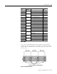
Figure B.7 1784-PM02AE-TP0x Cable
Catalog Numbers for premade Servo card to termination panel cables.
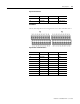
Pinouts for Cable 1784-PM02AE-TP0x
Allen-Bradley Catalog
Number
Length in
meters
1784-PM02AE-TP01 1m
1784-PM02AE-TP03 3m
Pin
(PX)
Pin Pair
Number
Pin Description Pin
(PY)
1 Pair 1 +CH A Feedback Input Axis 0 1
35 -CH A Feedback Input Axis 0 35
2 Pair 2 +CH B Feedback Input Axis 0 2
36 -CH B Feedback Input Axis 0 36
3 Pair 3 +CH Z Feedback Input Axis 0 3
37 -CH Z Feedback Input Axis 0 37
4 Pair 4 +OUT, Axis 0 4
38 -OUT, Axis 0 38
5 Pair 5 DRVFLT, Axis 0 5
49 HOME, Axis 0 49
6 Pair 6 REG1, Axis 0 6
40 REG2, Axis 0 40
7 Pair 7 +ENABLE, Axis 0 7
41 -ENABLE, Axis 0 41