
Configuration Manual Owner's manual

Publication 1784-UM003A-EN-P – June 2003
Naming & Configuring Your Motion Axis 125
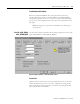
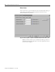
Tune
Select the gains to be determined by the tuning test:
• Position Error Integrator
• Velocity Feedforward
• Output Filter
• Velocity Error Integrator
• Acceleration Feedforward
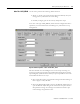
Start Tuning
Click on this button to begin the tuning test. If the tuning process completes
successfully the following attributes are set.
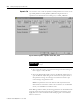
The Tune Bandwidth dialog opens for Servo drives, where you can "tweak"
bandwidth values.
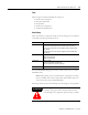
Note: During tuning, if the controller detects a high degree of tuning
inertia, it enables the Low Pass Output Filter and calculates and sets a
value for Low Pass Output Filter Bandwidth.
Executing a Tune operation automatically saves all changes to axis properties.
On this tab: These attributes are set:
Gains tab Velocity Feedforward Gain (if checked under Tune, above)
Acceleration Feedforward Gain (if checked under Tune, above)
Position Proportional Gain Position Integral Gain (if checked under
Tune, above)
Velocity Proportional Gain Velocity Integral Gain (if checked under
Tune, above)
Dynamics tab Maximum Velocity
Maximum Acceleration
Maximum Deceleration
Output tab Torque Scaling
Velocity Scaling (AXIS_SERVO only)
Low Pass Output Filter (see Note, below)
Limits Position Error Tolerance
ATTENTION
!
This tuning procedure may cause axis motion with the
controller in program mode. Unexpected motion may
cause damage to the equipment, personal injury, or death.