SoftLogixTM Motion Card (Cat.No.
Important User Information Because of the variety of uses for the products described in this publication, those responsible for the application and use of this control equipment must satisfy themselves that all necessary steps have been taken to assure that each application and use meets all performance and safety requirements, including any applicable laws, regulations, codes and standards.
European Communities (EC) Directive Compliance If this product has the CE mark it is approved for installation within the European Union and EEA regions. It has been designed and tested to meet the following directives.
Table of Contents Preface Using This Manual Who Should Use This Manual. . . . . . . . . . . . . . . . . . . . . . . . . . . . . . . . . 1 The Purpose of This Manual . . . . . . . . . . . . . . . . . . . . . . . . . . . . . . . . . . 1 Related Documentation . . . . . . . . . . . . . . . . . . . . . . . . . . . . . . . . . . . . . . 2 Rockwell Automation Support . . . . . . . . . . . . . . . . . . . . . . . . . . . . . . . . 2 Local Product Support . . . . . . . . . . . . . . . . . . . . . . . . . . . . . .
ii Chapter 4 Configuring the1784-PM16SE Card Adding the 1784-PM16SE . . . . . . . . . . . . . . . . . . . . . . . . . . . . . . . . . . . 61 SERCOS interface Motion Card Overview . . . . . . . . . . . . . . . . . . . . . 66 Editing 1784-PM16SE Card Properties . . . . . . . . . . . . . . . . . . . . . . . . 67 Chapter 5 The Motion Group Creating A Motion Group . . . . . . . . . . . . . . . . . . . . . . . . . . . . . . . . . . . 79 Editing the Motion Group Properties. . . . . . . . . . . . . . . . . . . .
iii Chapter 12 Motion Instructions Motion State Instructions . . . . . . . . . . . . . . . . . . . . . . . . . . . . . . . . . . 253 Motion Move Instructions. . . . . . . . . . . . . . . . . . . . . . . . . . . . . . . . . . 254 Motion Group Instructions . . . . . . . . . . . . . . . . . . . . . . . . . . . . . . . . . 255 Motion Event Instructions . . . . . . . . . . . . . . . . . . . . . . . . . . . . . . . . . 255 Motion Configuration Instructions . . . . . . . . . . . . . . . . . . . . . . . . . . .
iv Chapter 14 Troubleshooting 1784-PM02AE LED Indicator . . . . . . . . . . . . . . . . . . . . . . . . . . . . . . 411 SERCOS interface LED Indicators . . . . . . . . . . . . . . . . . . . . . . . . . . 412 Appendix A Specifications and Performance 1784-PM02AE Motion Card Specifications . . . . . . . . . . . . . . . . . . . . 417 1784-M16SE Motion Card Specifications. . . . . . . . . . . . . . . . . . . . . .
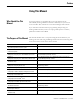
Preface Using This Manual Who Should Use This Manual To use this manual, you should be able to program and operate the Allen-Bradley SoftLogix5800™ controllers to efficiently use your motion control modules. The manual’s focus is from the RSLogix 5000 software. If you need more information about programming and operating the SoftLogix5800 controllers, refer to the SoftLogix5800 System User Manual, publication number 1789-UM002.
2 Using This Manual Appendix A Specifications Specifications and performance guidelines for the motion card. Appendix B Loop and Interconnect Diagrams Loop diagrams and wiring diagrams for your SoftLogix motion control system.
Using This Manual 3 Local Product Support Contact your local Rockwell Automation representative for: • sales and order support • product technical training • warranty support • support service agreements Technical Product Assistance If you need to contact Rockwell Automation for technical assistance, please review the information in this manual. If the problem persists, call your local Rockwell Automation representative.
4 Using This Manual Publication 1784-UM003A-EN-P – June 2003
Chapter 1 The SoftLogix Motion Control System This chapter describes the SoftLogix motion control system and its components. SoftLogix Motion Control The Virtual Chassis, SoftLogix controller, 1784-PM02AE servo card, 1784-PM16SE SERCOS interface card, and RSLogix 5000 programming software provide integrated motion control support.
6 The SoftLogix Motion Control System Figure 1.1 SoftLogix System with 1784-PM02AE Figure 1.
The SoftLogix Motion Control System 7 SoftLogix Chassis Monitor It is at the Chassis Monitor where you can change the processor mode, and view system status. After you have created and configured the various modules of your SoftLogix system you can use the Chassis Monitor to display the virtual chassis where you can monitor the simulated LEDs to view status information for your modules. Figure 1.
8 The SoftLogix Motion Control System Additional information in the form of a tooltip about the modules can be ascertained by placing the mouse over a specific module. Figure 1.4 Additional Information for the PM16SE Card The SoftLogix Controller The SoftLogix controller is the main component in the SoftLogix system. It supports sequential and motion functions, and it performs all of the motion command execution and motion trajectory planner functions.
The SoftLogix Motion Control System 9 The Analog/Encoder Servo Module The Analog/Encoder servo module provides an analog/quadrature encoder (1784-PMO2AE) servo drive interface. The servo module receives configuration and move information from the SoftLogix controller and manages motor position and velocity.
10 The SoftLogix Motion Control System Developing a Motion Control Application Program This section provides an introduction to concepts used in developing application programs for motion control.
The SoftLogix Motion Control System ATTENTION ! 11 Tags used for the motion control parameter of instructions should only be used once. Re-use of the motion control parameter in other instructions can cause unintended operation of the control variables. For more information about the MOTION_INSTRUCTION tag, refer to the Logix5000 Controller Motion Instruction Set Reference Manual (1756-RM007).
12 The SoftLogix Motion Control System Handling Motion Faults Two types of motion faults exist.
Chapter 2 SoftLogix Controller Introduction Before you can begin programming or configuring your controller, you must create a project file in which to store it. To create a Project: 1. From the Type pull-down menu, choose the controller type that you wish to use for this project. 2. Enter the name you wish to use for the controller. The same name is used for the project file with the .acd extension. 3. Enter a description of the controller. 4.
14 SoftLogix Controller In addition, if you have chosen a FlexLogix controller, 2 FlexBus adapters are created in slots 3 and 4 under the I/O Configuration folder. These 2 folders contain all local I/O for FlexLogix, other than the 2 local slots for communication. The first folder contains all I/O configured on the local Flex rail housing the Flex controller; the second folder contains all I/O configured for the local non-controller rail.
SoftLogix Controller 15 Vendor Displays the name of the controller’s manufacturer. Type Select the controller type from the pull-down menu, shown here by catalog number, platform, and processor.
16 SoftLogix Controller Chassis Type Select the appropriate chassis type from the pull-down menu, shown here by catalog number. The software uses this information to determine the number of slots in the chassis.
SoftLogix Controller Editing Controller Properties 17 The Controller Properties dialog displays controller configuration information for the open project and, when online, for the attached controller. The Tabs that appear are governed by the type of the selected controller. This section describes the fields on each of the dialogs for the Controller Properties. General Tab The General tab displays the controller name and description, as well as the physical properties of the controller. Figure 2.
18 SoftLogix Controller Name The name of the controller. When you create a project, this is the same as the name of the project file. When you change the name of the controller, however, the name of the project file does not change. If you want to keep the two the same, then you must rename the file using Windows Explorer or a similar file management tool. IMPORTANT This name must be IEC_1131 compliant.
SoftLogix Controller 19 Change Controller Type Dialog Box Use this dialog to change your controller to another controller within the same Overview platform (e.g. changing from a 1756-L1 ControlLogix 5550 Controller to a 1756-L53/A ControlLogix 5553 controller). Figure 2.3 Change Controller Type Dialog Select a processor to change to Choose the controller you wish to change to from the pull-down menu. The list of available controllers includes all controller types except the current processor itself.
20 SoftLogix Controller Serial Port Tab The Serial Port tab allows you to view and configure the controller’s serial port. Figure 2.5 Controller Properties Serial Port Tab Mode The type of protocol you want to use. Choose from System or User (default). Baud Rate The baud rate assigned to the serial port on the Logix5550. Choose from 110, 300, 600, 1200, 2400, 4800, 9600, 19200 (default), and 38,400. Data Bits The actual number of bits of data per character. Choose from 7 (ASCII only) or 8 (default).
SoftLogix Controller 21 Stop Bits The actual number of stop bits per character. Choose from 2 (ASCII only) or 1 (default). Control Line Choose the type of handshaking you wish to use during communications.
22 SoftLogix Controller System Protocol Tab The System Protocol tab allows you to configure the controller’s serial port for DF1 Point to Point, DF1 Master, DF1 Slave or DH485. The parameters present on this tab are dependent upon the protocol you select. Figure 2.6 Controller Properties System Protocol Tab IMPORTANT If you wish to configure your system for ASCII, click on the User Protocol tab. The parameters present on this tab are dependent upon the protocol you select.
SoftLogix Controller 23 Error Detection Click on one of the radio buttons to specify the error detection scheme used for all messages. • BCC - the processor sends and accepts messages that end with a BCC byte. • CRC - the processor sends and accepts messages with a 2-byte CRC. Enable Duplicate Detection Check this box to enable duplicate message detection, which causes the object to ignore all duplicate messages. This option is disabled by default.
24 SoftLogix Controller DF1 Slave Parameters Transmit Retries Enter the number of attempted transmits without getting an acknowledgment before a message is deemed undeliverable. Valid values are from 0 to 255; the default value is 3. Slave Poll Timeout Enter the amount of time that the master waits for an acknowledgment to a message sent to the slave. EOT Suppression Check this box if you want to suppress "End of Text" transmissions at the end of a slave message.
SoftLogix Controller 25 Master Transmit Choose the master message transmit that designates when to send any DF1 master message. Choose from: • Between Station Polls - The master transmits a message before the next station. • In Poll Sequence - The master transmits messages only when the station number is encountered in the poll list. The default is Between Station Polls. Normal Poll Node Tag Choose the tag name of the structure that contains the normal poll node list.
26 SoftLogix Controller Token Hold Factor A value between 1 and 4. User Protocol Tab The User Protocol tab allows you to configure the controller’s serial port for the ASCII protocol. Figure 2.7 Controller Properties User Protocol Protocol Choose the ASCII protocol. Buffer Size Enter the maximum size (in bytes) of the data array that you are planning on sending and receiving. Valid values are from 1 to 65536; the default size is 82.
SoftLogix Controller 27 Termination Character 1 and 2 Enter the characters that be used to define the end of a line. Valid hex range values are from 0 to 255. The default value for Termination Character 1 is $0D, and the default value for Termination Character 2 is $FF. The ARL and ABL instructions use these characters to signal the end of a line.
28 SoftLogix Controller This option is disabled when the Control Line option is configured for Half Duplex. Delete Mode The character received just before the delete character sequence (0x7F) is removed by the serial port driver before it is given to the ladder logic. Choose from: • Ignore - The delete character sequence is treated the same as any other character that is read in. • CRT or Printer - The preceding character in the string buffer is removed before being given to the ladder logic.
SoftLogix Controller 29 Number of Major Faults Since Last Cleared Displays the number of major fault events that have been reported since the log was last cleared. Recent Faults Displays a description of the last three major faults that have occurred. These faults are stored in reverse chronological order. When offline, this field contains the stored contents of the last online session. Clear Majors Click on this button to clear the Major Fault log.
30 SoftLogix Controller Recent Faults Displays a description of the last eight minor faults that have occurred. These faults are stored in reverse chronological order. When offline, this field contains the stored contents of the last online session. Clear Minors Click on this button to clear the Minor Fault log. Fault Bits Lists the minor fault bits that have a specific fault type assigned to them. If the bit is set, the checkbox is set.
SoftLogix Controller 31 Date The wall clock date, in the format currently selected in the Regional Settings application in your Windows NT Control Panel. This parameter is read-only. When offline, this parameter is empty. Time The wall clock time, in the format currently selected in the Regional Settings application in your Windows NT Control Panel. This parameter is read-only. When offline, this parameter is empty.
32 SoftLogix Controller All of the circular indicators are clear when you are offline. Advanced Tab The Advanced tab allows you to view and edit advanced controller properties. Figure 2.11 Controller Properties Advanced Tab Memory Used The amount of memory used in the controller. When offline, this parameter is empty. Memory Unused The amount of memory available in the controller. When offline, this parameter is empty. Memory Total The total amount of memory in the controller (used plus unused).
SoftLogix Controller 33 Controller Fault Handler Choose the program that runs as the result of a system fault from the pull-down menu. The list contains all of the unscheduled programs. Power-Up Handler Choose the program the processor executes when it powers up in Run mode after a power-down in Run mode. The list contains all of the unscheduled programs. System Overhead Time Slice Enter or select the percentage of time the controller spends running its system task, relative to running user tasks.
34 SoftLogix Controller Execution Control This determines the execution model for the SFC. Your options are: • Execute current active steps only – Execution control is returned to the controller after processing the active steps, even if the Transitions following the active steps are True. • Execute until False transition – The controller continually processes Steps and Transitions, in a single scan, until a False Transition is found. It then returns to the Controller operating system.
SoftLogix Controller 35 File Tab The File tab displays information about the project file. The fields on this tab cannot be edited. To change the file name or path, you must use the Save As command. Figure 2.13 Controller Properties File Tab Name The name of the project file Path The drive and directory of the project file. Created The creation date and time of the project file, in the format currently selected in the Regional Settings application in your Windows NT Control Panel.
36 SoftLogix Controller Redundancy Tab The Redundancy Tab is only present if the specified processor type and version supports the Redundancy feature. This tab supports the configuration for redundancy. Figure 2.14 Controller Properties Redundancy Tab Redundancy Enabled This checkbox lets you select whether to enable the redundancy feature or not. It can only be selected when the Controller is offline. When it is on-line it provides a valid indication of the redundancy enabled selection.
SoftLogix Controller 37 4 – Primary with no partner 8 – Synchronized Secondary 9 – Disqualified Secondary with partner 10 – Disqualified Secondary with no partner Module State – Indicates the redundancy state of the controller. If the controller does not have the redundancy feature or if it is offline, this field is empty and the controls are disabled. The possible states include: 0 – Unsupported – also displays when the system is offline.
38 SoftLogix Controller Partner Status This section shows information on the status of the Partner module. Mode – Shows the current state of the partner module’s mode. If the controller does not have the redundancy feature or if it is offline, this field is empty and the controls are disabled. Valid modes include: • Faulted • Run • Program • Test • Unknown – Displayed for any mode that is not one of those listed above.
SoftLogix Controller 39 Advanced Button The Advanced Button displays configuration parameters for retaining test edits when switched to a secondary system and lets you set the percentage of memory that is reserved for the data table. Figure 2.15 Advanced Button from Redundancy Tab Retain Test Edits on Switchover Select the checkbox to allow temporary execution of online edits to be maintained or canceled when a switchover to a secondary system occurs.
40 SoftLogix Controller Click on the Load/Store button to access the Nonvolatile Memory Load/Store dialog, from which you can perform the actual operations. The Nonvolatile Memory tab also provides you with status information that indicates any conditions that might prevent you from loading or storing. Possible status messages include: • Nonvolatile memory not present. • Nonvolatile memory not supported in redundant systems. • Controller being edited by another user.
SoftLogix Controller 41 Figure 2.16 Controller Properties Nonvolatile Memory Tab Name The name of the stored controller image that resides in nonvolatile memory. Type The controller type for the image stored in nonvolatile memory. This controller type can be any type that supports nonvolatile memory. Revision The firmware revision of the controller when the image in nonvolatile memory was stored.
42 SoftLogix Controller Load Image The condition under which the image stored in nonvolatile memory is loaded back to controller memory. Available conditions include: • On Corrupt Memory – this will cause a load whenever there is no project in the controller and you turn on or cycle power on the chassis. If you are using a battery the controller, selecting this option performs a load only if the battery has failed to maintain the project during a loss of power.
SoftLogix Controller 43 Stored The workstation date and time when the image was stored in nonvolatile memory. Load/Store Click on this button to access the Load/Store dialog. This button is disabled when: • Nonvolatile memory is not present in the controller. • The controller is in Run mode. • Another user has locked the controller. • Redundancy is enabled for the controller. • The controller is offline. If the Load/Store button is disabled, the status bar indicates the reason.
44 SoftLogix Controller Publication 1784-UM003A-EN-P – June 2003
Chapter 3 Adding and Configuring Your 1784-PM02AE Motion Module This chapter describes how to add, configure, and edit your 1784-PM02AE motion module for use in your motion control application. Adding the 1784-PM02AE Module To use your motion module in a control system, you must add your motion module to the application program. To add a motion module: 1. Right-click the I/O Configuration folder. Figure 3.
46 Adding and Configuring Your 1784-PM02AE Motion Module 2. Select New Module. The Select Module Type window appears. Figure 3.
Adding and Configuring Your 1784-PM02AE Motion Module 47 3. Click on the Clear All button to clear the dialog window then click on Motion to list the available Motion Controllers. Figure 3.3 Select Module Type Screen with Motion Options - M02AE Highlighted New Module Use this dialog to select and create a new module. Highlight the 1784-PM02AE The context sensitive menu appears, from which you can select a New Module.
48 Adding and Configuring Your 1784-PM02AE Motion Module Major Revision Select the major revision number of the physical module that you want in the chassis. The major revision is used to indicate the revision of the interface to the module. Type (list box) This box lists the installed module catalog numbers based on the selected check boxes. Description (list box) This portion of the list box contains descriptions of the modules.
Adding and Configuring Your 1784-PM02AE Motion Module 49 5. Select OK. The Module Create Wizard displays. Figure 3.4 Module Properties Dialog Wizard - Naming the Module 6. Make entries in the following fields. Field Entry Name Type a name for the servo module. The name can: • have a maximum of 40 characters • contain letters, numbers and underscores (_). Slot Enter the number of the chassis slot that contains your module. Description Type a description for your motion module.
50 Adding and Configuring Your 1784-PM02AE Motion Module 7. Press the Next button to proceed to the next Create Wizard screen. Figure 3.5 Module Properties Wizard - Fault Handling 8. This screen is where you determine how faults are to be handled. The choices are to inhibit module or to configure the module so that a loss of connection to this module causes a major fault. Make your entries and press the Next button to proceed to the next wizard screen. Figure 3.
Adding and Configuring Your 1784-PM02AE Motion Module 51 9. This screen lets you associate an axis with the module. Make the appropriate choices for your application. At this point, the rest of the screens are informational only and it would be best to press the Finish button to create the module. All of the above screens can be accessed and edited by going to the tabbed Module Property screens. Further explanations of the fields in this dialog are detailed below.
52 Adding and Configuring Your 1784-PM02AE Motion Module This accesses the Module Properties screen. The screen is tabbed to expedite movement to the required dialog. Figure 3.8 Module Properties - General Tab General Tab Use this tab to create/view module properties for 1784-PM02AE motion module. This dialog provides you with the means to view the type, description, vendor, and the name of the parent module. You can also enter the name and a description for the module.
Adding and Configuring Your 1784-PM02AE Motion Module 53 The name must be IEC 1131-3 compliant. If you attempt to enter an invalid character or exceed the maximum length, the software beeps and ignores the character. Description Enter a description for the module here, up to 128 characters. You can use any printable character in this field. If you exceed the maximum length, the software beeps to warn you, and ignores any extra characters. Slot Enter the slot number where the module resides.
54 Adding and Configuring Your 1784-PM02AE Motion Module When you insert a module into a slot in a ControlLogix chassis, RSLogix 5000 compares the following information for the inserted module to that of the configured slot: • Vendor • Product Type • Catalog Number • Major Revision • Minor Revision This feature prevents the inadvertent insertion of the wrong module in the wrong slot. Connection Tab The Connection Tab is used to define controller to module behavior.
Adding and Configuring Your 1784-PM02AE Motion Module 55 Inhibit Module checkbox Check/Uncheck this box to inhibit/uninhibit your connection to the module. Inhibiting the module causes the connection to the module to be broken.
56 Adding and Configuring Your 1784-PM02AE Motion Module Module Fault Displays the fault code returned from the controller (related to the module you are configuring) and the text detailing the Module Fault that has occurred. The following are common categories for errors: • Connection Request Error - The controller is attempting to make a connection to the module and has received an error . The connection was not made.
Adding and Configuring Your 1784-PM02AE Motion Module 57 Servo Update Period Selects the periodic rate at which the 1784-PM02AE module closes the servo loop for the axis, in microseconds (µs). Channel 0 Represents Channel 0 on the servo module. This field allows you to associate an AXIS_SERVO tag with channel 0. This field transitions to a read-only state while online. Click on the button to the right of this field to open the Axis Properties dialog for the associated axis.
58 Adding and Configuring Your 1784-PM02AE Motion Module The data on this tab comes directly from the module. If you selected a Listen-Only communication format when you created the module, this tab is not available. Figure 3.11 Module Properties - Module Info Tab Identification Displays the module’s: • Vendor • Product Type • Product Code • Revision Number • Serial Number • Product Name The name displayed in the Product Name field is read from the module. This name displays the series of the module.
Adding and Configuring Your 1784-PM02AE Motion Module 59 Major/Minor Fault Status If you are configuring a: This field displays one of the following: digital module EEPROM fault Backplane fault None analog module Comm. Lost with owner Channel fault None any other module None Unrecoverable Recoverable Internal State Status This field displays the module’s current operational state.
60 Adding and Configuring Your 1784-PM02AE Motion Module Module Identity Displays: If the module in the physical slot: Match agrees with what is specified on the General Tab.
Chapter 4 Configuring the1784-PM16SE Card Adding the 1784-PM16SE This chapter reviews the necessary steps for configuring the 1784-PM16SE motion card. Much of this information is the same as for adding and configuring the 1784-PM02AE as discussed in the previous chapter. To configure a 1784-PM16SE motion card: 1. In the Controller Organizer, right mouse click on I/O Configuration. Figure 4.1 Controller Organizer | I/O Configuration| New Module 2.
62 Configuring the1784-PM16SE Card 3. The Select Module Type screen displays. Select Clear All. Select Motion. The list displays only available motion modules. Figure 4.3 Select Module Type Screen with Motion Options - 1784-PM16SE Selected 4. Select 1784-PM16SE. 5. Press the OK button to close the Select Module Type dialog.
Configuring the1784-PM16SE Card 63 6. The Create Module Wizard opens. Figure 4.4 Module Properties Wizard Dialog - Name the Module 7. Name is the only required field that must be entered to create the 1784-PM16SE card. It must conform to the IEC 1131-3 standard. You can also enter a description for the card, select the minor revision number of your card, and select the method for Electronic Keying.
64 Configuring the1784-PM16SE Card 8. The Connection Screen Wizard displays. Figure 4.5 Module Properties Wizard Dialog - Connection Screen 9. On this screen there are no required fields but you can enter how you want to handle connection faults. The Requested Packet Interval (RPI) field does not pertain to the SERCOS interface cards and is greyed out. Inhibit Module defaults to Unchecked. Click on the check box to inhibit the module. Major Fault on Controller ... check box defaults to uncheck.
Configuring the1784-PM16SE Card 65 10. The SERCOS interface screen displays. Figure 4.6 Module Properties Wizard Dialog - SERCOS interface Screen 11. On this screen you can enter the Data Rate, SERCOS ring Cycle time, and the transmit power for the SERCOS ring. The rest of the Create Wizard screens are only informational and do not let you enter any information. It saves time if you click on the Finish>> button at this time. 12.
66 Configuring the1784-PM16SE Card SERCOS interface Motion Card Overview The 1784-PM16SE SERCOS interface motion card has been added. To edit the 1784-PM16SE card properties, go to the I/O Configuration organizer and right click on the 1784-PM16SE card and select Properties from the drop down menu. The tabbed Module Properties screen displays. Figure 4.7 Module Properties - General Tab The Module Properties screen has the following tabs: • The General tab references the 1784-PM16SE motion card.
Configuring the1784-PM16SE Card 67 Editing 1784-PM16SE Card Properties General Tab Use this tab to create/view module properties for the 1784-PM16SE motion card.
68 Configuring the1784-PM16SE Card Slot Enter the slot number where the card resides. The spin button contains values that range from 0 to 1 less than the chassis size (e.g., if you have a 4-slot chassis, the spin button spins from 0 to 3). Only available slot numbers are listed by the spin button. However, you can edit the slot number manually. If you enter a slot number that is out of this range, you receive an error message when you apply your changes. The slot number cannot be changed when online.
Configuring the1784-PM16SE Card 69 Status – This is a Read Only field that displays the Controllers current opinion of the card. Standby – A transient state that occurs when shutting down. Faulted – It is unable to communicate with the card. When Faulted is displayed, check the Connection Tab fore the fault listing. Validating – A transient state that occurs prior to connecting to the card. Connecting – The state while the connection(s) to the cards are established.
70 Configuring the1784-PM16SE Card Connection Tab The Connection Tab reflects controller to card behavior. This is where you choose to inhibit the card, configure the controller so loss of the connection to this card causes a major fault, and view card faults when online. Figure 4.8 Module Properties - Connection Tab The fault data on this tab comes directly from the controller. This tab displays information about the condition of the connection between the card and the controller.
Configuring the1784-PM16SE Card ATTENTION 71 Inhibiting the card causes the connection to the card to be broken and may result in loss of data. ! When you check this box and go online, the icon representing this card in the controller organizer displays the Attention Icon.
72 Configuring the1784-PM16SE Card • Service Request Error - The controller is attempting to request a service from the card and has received an error. The service was not performed successfully. • Module Configuration Invalid - The configuration in the card is invalid. (This error is commonly caused by the Electronic Key Passed fault). • Electronic Keying Mismatch - Electronic Keying is enabled and some part of the keying information differs between the software and the card.
Configuring the1784-PM16SE Card 73 The SERCOS ring consists of the drives and axes connected to the 1784-PM16SE motion controller. TIP The settings on this tab are specific to the 1784-PM16SE motion controller. Data Rate Select the baud rate for the SERCOS ring. Your options are: • Auto Detect – automatically scans to detect the SERCOS ring baud rate as set by the drive(s). • 4 Mb – sets the SERCOS ring baud rate to 4 Mb. This value must match the baud rate set on the drives.
74 Configuring the1784-PM16SE Card Transmit Power Select the optic transmit power range for the SERCOS ring: • High • Low It is recommended that you set to High. SERCOS Interface Info Tab The SERCOS interface Tab is for monitoring the SERCOS ring of the selected 1784-PM16SE while it is on-line. A REFRESH button is available to access the current values. Figure 4.10 Module Properties - SERCOS Interface Info Tab Use this tab to monitor the following: Ring Comm.
Configuring the1784-PM16SE Card 75 Fault Type Displays the current fault type, if any, on the SERCOS ring. Values include: • No fault • Loss of received signal • MST error • Missed AT • Excessive AT errors • Duplicate nodes (not currently supported) • No nodes • Wrong ring cycle • Wrong baud rate • Link transport fault • Wrong phase • Wrong AT number Refresh Click this button to update this page. Note: this information does not refresh automatically.
76 Configuring the1784-PM16SE Card The data on this tab comes directly from the card. If you selected a Listen-Only communication format when you created the card, this tab is not available. Figure 4.11 Module Properties - Module Info Tab Identification Displays the card’s: • Vendor • Product Type • Product Code • Revision Number • Serial Number • Product Name The name displayed in the Product Name field is read from the card. This name displays the series of the card.
Configuring the1784-PM16SE Card 77 Major/Minor Fault Status If you are configuring a: This field displays one of the following: digital card EEPROM fault Backplane fault None analog card Comm. Lost with owner Channel fault None any other card None Unrecoverable Recoverable Internal State Status This field displays the card’s current operational state.
78 Configuring the1784-PM16SE Card Module Identity Displays: If the card in the physical slot: Match agrees with what is specified on the General Tab.
Chapter 5 The Motion Group Creating A Motion Group Each .acd program must have one motion group. (There can be only one.) You must create it before an axis can be assigned to the group and have it function within the .acd program. To create the motion group, right click on Motion Group and select New Motion Group from the drop down menu. Figure 5.1 Controller Organizer - New Motion Group Pop-up This calls the New Tag window. Figure 5.2 New Tag Dialog 1.
80 The Motion Group 3. Click on the respective radio button to select one of the following tag types: • Base - refers to a normal tag (selected by default) • Alias - refers to a tag, which references another tag with the same definition. Special parameters appear on the New Tag dialog that allows you to identify to which base tag the alias refers. 4. Select MOTION_GROUP for the Data Type. 5. From the Scope pull-down menu, select the scope for the tag. 6.
The Motion Group 81 The Motion Group Wizard group - Axis Assignment screen displays. Figure 5.3 Motion Group Wizard Dialog - Axis Assignment Add any existing axes to the group. 8. Continue on through the Motion Group Wizard to configure your Motion Group tag as necessary. Click on Finish>> to close the wizard.
82 The Motion Group Editing the Motion Group Properties The Motion Group properties can be edited by right clicking on the group name and selecting Motion Group Properties from the drop down menu. Figure 5.4 Controller Organizer | Motion Group| Properties The Motion Group Properties tabbed screen displays. Figure 5.
The Motion Group 83 Axis Assignment Tab The Axis Assignment screen is where axes are either assigned or unassigned to the Motion Group. When RSLogix 5000 software is online, all attributes on this dialog transition to a read-only state. When an attribute transitions to a read-only state, all pending attribute changes revert back to their offline status. Unassigned Lists the axes that are not assigned to any group in the controller. Assigned Lists the axes that are assigned to this motion group.
84 The Motion Group When RSLogix 5000 software is online, all of the attributes on this tab transition to a read-only state. When an attribute transitions to a read-only state, all pending attribute changes are reverted. Coarse Update Period Selects the periodic rate at which the motion task executes to compute the servo commanded position, velocity, and accelerations to be sent to the 1784-PM02AE or 1784-PM16SE modules when executing motion instructions.
The Motion Group 85 Tag Tab Use this tab to modify the name and description of the group. Figure 5.7 Motion Group Properties - Tag Tab When you are online, all of the parameters on this tab transition to a read-only state, and cannot be modified. If you go online before you save your changes, all pending changes revert to their previously-saved state. Name Enter the name of the motion group. This name must not exceed 40 characters.
86 The Motion Group Data Type (read-only) The axis data type: MOTION_GROUP Scope Displays the scope of the current tag. The scope is either controller scope, or program scope, based on one of the existing programs in the controller. Style Not applicable to motion group tags. Produce this tag for up to A checked box indicates that this tag is available to remote controllers through controller-to-controller messaging. If this box is checked, the system displays the maximum number of consumers (i.e.
Chapter 6 Naming & Configuring Your Motion Axis This chapter describes how to name, configure, and edit your axis properties. Be careful while reading this information. Many of the screens appear to be the same (and many are) but some of the screens change in content based on the type of axis. They are labeled where different so read through the entire section to make sure you find the explanations for the type of axis selected. Naming an Axis Naming an axis adds it to your application.
88 Naming & Configuring Your Motion Axis You can also right click on the Motion Group and select New Axis and the type of axis tag you want to create from the menu. Figure 6.2 Naming an Axis From Motion Group You can also initiate a new axis by right clicking on Ungroup Axes and selecting the type of axis you want to create. Figure 6.
Naming & Configuring Your Motion Axis 89 The New Tag window appears. Figure 6.4 New Tag Dialog If you accessed the New Tag window from either Motion Group or Ungrouped Axes, the Data Type is already filled in. Entering Tag Information A tag allows you to allocate and reference data stored in the controller. A tag can be a simple, single element, or an array, or a structure. There are four types of tags that you can create: • A base tag allows you to create your own internal data storage.
90 Naming & Configuring Your Motion Axis You must set up only one consumed tag to get data from the same producing tag in another controller. ATTENTION Setting up more than one consumed tag results in unpredictable controller to controller behavior. ! Use this dialog to create new tags. The parameters that appear on this dialog depend upon the type of tag you are creating. You can create base tags and alias tags while the controller is online or offline, as long as the new tag is verified.
Naming & Configuring Your Motion Axis 91 Data Type In the Data Type field you can either enter the type of tag you want to create directly or click on the ellipsis button to go to the Select Data Type dialog. From this dialog you can select the appropriate axis data type: AXIS_CONSUMED, AXIS_SERVO, AXIS_SERVO_DRIVE, or AXIS VIRTUAL. Make entries in the following fields. Editing Motion Axis Properties Field Entry Name Type a name for the servo axis.
92 Naming & Configuring Your Motion Axis In the Controller Organizer, right click on the axis to edit and select Axis Properties from the drop down menu. Figure 6.5 Accessing Axis Properties from Controller Organizer The Axis Properties General window appears. The General screen depicted below is for an AXIS_SERVO data type. Figure 6.
Naming & Configuring Your Motion Axis 93 The General screen shown below is for an AXIS_SERVO DRIVE Data Type. Figure 6.7 Axis Properties - General Tab for Axis_Servo_Drive The AXIS_VIRTUAL General Tab is shown below. Figure 6.
94 Naming & Configuring Your Motion Axis General Tab – AXIS_SERVO Use this tab to do the following for an axis, of the data type AXIS_SERVO: • Configure the axis for Servo operation, or for position Feedback Only. • Assign the axis, or terminate the assignment of an axis, to a Motion Group. • Associate the axis with a 1784-PM02AE motion module. • Select the channel, 0 or 1, on the 1784-PM02AE motion module to which the axis is connected.
Naming & Configuring Your Motion Axis 95 New Group button Opens the New Tag dialog box, where you can create a new Motion Group tag. This button is enabled only if no Motion Group tag has been created. Module Selects and displays the name of the motion module to which the axis is associated. Displays if the axis is not associated with any motion module. Module Type This read-only field displays the type of motion module, if any, with which the axis is associated.
96 Naming & Configuring Your Motion Axis Axis Configuration Selects and displays the intended use of the axis: • Feedback Only: If the axis is to be used only to display position information from the feedback interface. This selection minimizes the display of axis properties tabs and parameters. • Servo: If the axis is to be used for full servo operation. This selection maximizes the display of axis properties tabs and parameters.
Naming & Configuring Your Motion Axis 97 General Tab - AXIS_VIRTUAL Use this tab to associate the axis, of the data type AXIS_VIRTUAL, to a Motion Group. Note: RSLogix 5000 supports only one Motion Group tag per controller. When RSLogix 5000 software is online, the parameters on this tab transition to a read-only state. When a parameter transitions to a read-only state, any pending changes to parameter values are lost, and the parameter reverts to the most recently saved parameter value.
98 Naming & Configuring Your Motion Axis Press Apply then select the Motion Planner tab to access the Axis Properties Motion Planner dialog. Figure 6.9 Axis Properties – Motion Planner Tab Motion Planner Tab The Motion Planner Tab is where you set/edit the number of Output Cam execution targets, the type of stop action to use, enable or disable Master Delay Compensation, enable or disable Master Position Filter, and set the bandwidth for Master Position Filter Bandwidth.
Naming & Configuring Your Motion Axis 99 Program Stop Action Select how a specific axis is stopped when the processor undergoes a mode change, or when an explicit Motion Group Programmed Stop (MGPS) instruction is executed: • Fast Disable: The axis is decelerated to a stop using the current configured value for maximum deceleration. Servo action is maintained until the axis motion has stopped at which time the axis is disabled (i.e., Drive Enable is disabled, and Servo Action is disabled).
100 Naming & Configuring Your Motion Axis Enable Master Position Filter Checkbox Use this checkbox to Enable/Disable Master Position Filter. The default is disabled and must be checked to enable position filtering. Master Position Filter, when enabled, effectively filters the specified master axis position input to the slave axis’s gearing or position camming operation.
Naming & Configuring Your Motion Axis 101 Units Tab The Units Tab is the same for all axis data types. Use this tab to determine the units to define your motion axis. When RSLogix 5000 software is online and the controller transitions to hard run, or the servo loop is on (i.e., active), then all the attributes on this tab transition to a read only state. When any attribute transitions to a read only state, then any pending attribute changes are reverted.
102 Naming & Configuring Your Motion Axis Servo Tab - AXIS_SERVO Click on the Servo Tab from the Axis Properties for AXIS_SERVO to access the Servo dialog. Figure 6.
Naming & Configuring Your Motion Axis 103 External Drive Configuration Select the drive type for the servo loop: • Velocity - disables the servo module’s internal digital velocity loop. • Torque - the servo module’s internal digital velocity loop is active, which is the required configuration for interfacing the servo axis to a torque loop servo drive. Loop Configuration Select the configuration of the servo loop. For this release, only Position Servo is available.
104 Naming & Configuring Your Motion Axis Feedback Tab – (AXIS_SERVO) The Feedback Tab allows you to select the type of Feedback used with your Servo axis. Figure 6.12 Axis Properties - Feedback Tab for Axis_Servo Feedback Type Select the appropriate Feedback for your current configuration.
Naming & Configuring Your Motion Axis 105 Drive/Motor Tab - Use this tab to configure the servo loop for an AXIS_SERVO_DRIVE axis, (AXIS_SERVO_DRIVE) and open the Change Catalog dialog box. Figure 6.13 Axis Properties - Drive Tab for Axis_Servo_Drive When a parameter transitions to a read-only state, any pending changes to parameter values are lost, and the parameter reverts to the most recently saved parameter value.
106 Naming & Configuring Your Motion Axis Catalog Number Select the catalog number of the motor associated with this axis. When you change a Motor Catalog Number, the controller recalculates the values of the following values using (among other values) the default Damping Factor of 0.8.
Naming & Configuring Your Motion Axis 107 Drive Resolution Type in the number of counts per motor revolution. This value applies to all position data. Valid values range from 1 to 2^32 - 1. One Least Significant Bit (LSB) for position data equals 360° / Rotational Position Resolution. Note: Drive Resolution is also referred to as Rotational Position Resolution.
108 Naming & Configuring Your Motion Axis Figure 6.14 Change Catalog Screen Catalog Number Lists the available catalog numbers from the Motor Database based on any selection criteria from the Filters fields. Filters There are three optional Filter fields that allow you to refine your search of the Motor Database. The Filter boxes are defaulted to all. Voltage Lets you select a voltage rating from the pull-down list to broaden or narrow your search. The default is all.
Naming & Configuring Your Motion Axis 109 Motor Feedback Tab - Use this tab to configure motor and auxiliary feedback device (if any) AXIS_SERVO_DRIVE parameters, for an axis of the type AXIS_SERVO_DRIVE. Figure 6.15 Axis Properties - Motor/Feedback Tab for Axis_Servo_Drive Note: The Axis Configuration selection made on the General tab, and the Loop Configuration selection made on the Drive tab determine which sections of this dialog box – Motor and Auxiliary Feedback – are enabled.
110 Naming & Configuring Your Motion Axis Per The units used to measure the cycles. Interpolation Factor This field displays a fixed, read-only value for each feedback type. This value is used to compute the resolution of the feedback device. Aux Feedback Tab - The Auxiliary Feedback Tab is enabled only if the Drive tab’s Loop AXIS_SERVO_DRIVE Configuration field is set to Aux Feedback Only, Aux Position Servo, Dual Position Servo, Dual Command Servo, or Aux Dual Command Servo.
Naming & Configuring Your Motion Axis 111 Cycles The number of cycles of the auxiliary feedback device. This helps the Drive Compute Conversion constant used to convert drive units to feedback counts. Depending on the feedback type selected, this value may either be read-only or editable. Per The units used to measure the cycles. Interpolation Factor This field displays a fixed constant value for the selected feedback type. This value is used to compute the resolution of the feedback device.
112 Naming & Configuring Your Motion Axis The differences in the appearance of the Conversion Tab screens for the AXIS_SERVO and AXIS_SERVO_DRIVE are the default values for Conversion Constant and Position Unwind and the labels for these values. Figure 6.
Naming & Configuring Your Motion Axis 113 Positioning Mode This parameter is not editable for an axis of the data type AXIS_CONSUMED. Instead, this value is set in and taken from a producing axis in a networked Logix processor. This value can be edited for AXIS_SERVO, AXIS_SERVO_DRIVE and AXIS_VIRTUAL. The option are: • Linear - provides a maximum total linear travel of 1 billion feedback counts.
114 Naming & Configuring Your Motion Axis For axes of the type AXIS_SERVO_DRIVE: • when you save an edited Conversion Constant or a Drive Resolution value, a message box appears, asking you if you want the controller to automatically recalculate certain attribute settings. (Refer to Conversion Constant and Drive Resolution Attributes.) • the label indicates the number of counts per motor revolution, as set in the Drive Resolution field of the Drive tab. Click on Apply to accept your changes.
Naming & Configuring Your Motion Axis 115 Mode Select the homing mode: • Active: In this mode, the desired homing sequence is selected by specifying whether a home limit switch and/or the encoder marker is used for this axis. Active homing sequences always use the trapezoidal velocity profile. • Passive: In this mode, homing redefines the absolute position of the axis on the occurrence of a home switch or encoder marker event.
116 Naming & Configuring Your Motion Axis Sequence Select the event that causes the Home Position to be set: Sequence Type: Description: Immediate Sets the Home Position to the present actual position, without motion. Switch Sets the Home Position when axis motion encounters a home limit switch. Marker Sets the Home Position when axis encounters an encoder marker. Switch-Marker Sets the Home Position when axis first encounters a home limit switch, then encounters an encoder marker.
Naming & Configuring Your Motion Axis 117 Speed Type the speed of the jog profile used in the first leg of an active homing sequence. The homing speed specified should be less than the maximum speed and greater than zero. Return Speed The speed of the jog profile used in the return leg(s) of an active homing sequence. The home return speed specified should be less than the maximum speed and greater than zero.
118 Naming & Configuring Your Motion Axis Homing Tab - AXIS_VIRTUAL Use this tab to configure the attributes related to homing an axis of the type AXIS_VIRTUAL. Figure 6.20 Axis Properties - Homing Tab for Virtual Axis Data Type Only an Active Immediate Homing sequence can be performed for an axis of the type AXIS_VIRTUAL. When this sequence is performed, the controller immediately enables the servo drive and assigns the Home Position to the current axis actual position and command position.
Naming & Configuring Your Motion Axis 119 If the Positioning Mode (set in the Conversion tab) of the axis is Linear, then the home position should be within the travel limits, if enabled. If the Positioning Mode is Rotary, then the home position should be less than the unwind distance in position units. Sequence This read-only parameter is always set to Immediate. Hookup Tab - (AXIS_SERVO) Use this tab to configure and initiate axis hookup and marker test sequences for an axis of the type AXIS_SERVO.
120 Naming & Configuring Your Motion Axis Feedback Polarity The polarity of the encoder feedback, this field is automatically set by executing either the Feedback Test or the Output & Feedback Test: • Positive • Negative Note: When properly configured, this setting insures that axis Actual Position value increases when the axis is moved in the user defined positive direction. This bit can be configured automatically using the MRHD and MAHD motion instructions.
Naming & Configuring Your Motion Axis 121 Test Feedback Runs the Feedback Test, which checks and, if necessary, reconfigures the Feedback Polarity setting. When the test is initiated, you must manually move the axis one revolution for the system to detect the marker. If the marker is not detected, check the encoder wiring and try again.
122 Naming & Configuring Your Motion Axis Test Increment Specifies the amount of distance traversed by the axis when executing the Command & Feedback test. The default value is set to approximately a quarter of a revolution of the motor in position units. Drive Polarity The polarity of the servo loop of the drive, set by executing the Command & Feedback Test: • Positive • Negative Note: Proper wiring guarantees that the servo loop is closed with negative feedback.
Naming & Configuring Your Motion Axis 123 Test Command & Feedback Runs the Command & Feedback Test, which checks and, if necessary, reconfigures both the polarity of encoder feedback (the Feedback Polarity setting) and the polarity of the servo output to the drive (the Output Polarity setting), for an axis configured for Servo operation in the General tab of this dialog box. Note: Executing any test operation automatically saves all changes to axis properties.
124 Naming & Configuring Your Motion Axis Speed Determines the maximum speed for the tune process. This value should be set to the desired maximum operating speed of the motor (in engineering units) prior to running the tune test. Torque The maximum torque of the tune test. This attribute should be set to the desired maximum safe torque level prior to running the tune test. The default value is 100%, which yields the most accurate measure of the acceleration and deceleration capabilities of the system.
Naming & Configuring Your Motion Axis 125 Tune Select the gains to be determined by the tuning test: • Position Error Integrator • Velocity Feedforward • Output Filter • Velocity Error Integrator • Acceleration Feedforward Start Tuning Click on this button to begin the tuning test. If the tuning process completes successfully the following attributes are set.
126 Naming & Configuring Your Motion Axis Dynamics Tab Use this tab to view or edit the dynamics related parameters for an axis of the type AXIS_SERVO or AXIS_SERVO_DRIVE configured for Servo operations in the General tab of this dialog box, or AXIS_VIRTUAL. Figure 6.
Naming & Configuring Your Motion Axis 127 Maximum Velocity The steady-state speed of the axis, it is initially set to Tuning Speed by the tuning process. This value is typically set to about 90% of the maximum speed rating of the motor. This provides sufficient “head-room” for the axis to operate at all times within the speed limitations of the motor. Any change in value, caused by manually changing the spin control, is instantaneously sent to the controller.
128 Naming & Configuring Your Motion Axis Manual Adjust Click on this button to open the Dynamics tab of the Manual Adjust dialog for online editing of the Maximum Velocity, Maximum Acceleration, and Maximum Deceleration parameters. Figure 6.25 Axis Properties - Dynamics Tab Manual Adjust Screen for Axis_Servo Note: The Manual Adjust button is disabled when RSLogix 5000 is in Wizard mode, and when offline edits to the above parameters have not yet been saved or applied.
Naming & Configuring Your Motion Axis 129 Gains Tab - AXIS_SERVO Use this tab to perform the following offline functions: • adjust, or “tweak” gain values that have been automatically set by the tuning process (in the Tune tab of this dialog) • manually configure gains for the velocity and position loops for an axis of the type AXIS_SERVO, which has been configured for Servo operations (set in the General tab of this dialog box), with Position Loop Configuration. Figure 6.
130 Naming & Configuring Your Motion Axis Note: The parameters on this tab become read-only and cannot be edited when the controller is online if the controller is set to Hard Run mode, or if a Feedback On condition exists. When RSLogix 5000 is offline, the following parameters can be edited and the program saved to disk using either the Save command or by clicking on the Apply button. You must re-download the edited program to the controller before it can be run.
Naming & Configuring Your Motion Axis 131 Proportional (Position) Gain Position Error is multiplied by the Position Loop Proportional Gain, or Pos P Gain, to produce a component to the Velocity Command that ultimately attempts to correct for the position error. Too little Pos P Gain results in excessively compliant, or mushy, axis behavior. Too large a Pos P Gain, on the other hand, can result in axis oscillation due to classical servo instability.
132 Naming & Configuring Your Motion Axis While the Pos I Gain, if employed, is typically established by the automatic servo tuning procedure (in the Tuning tab of this dialog), the Pos I Gain value may also be set manually. Before doing this it must be stressed that the Output Scaling factor for the axis must be established for the drive system. Once this is done, the Pos I Gain can be computed based on the current or computed value for the Pos P Gain using the following formula: Pos I Gain = .025 * 0.
Naming & Configuring Your Motion Axis 133 Due to the destabilizing nature of Integral Gain, it is recommended that Position Integral Gain and Velocity Integral Gain be considered mutually exclusive. If Integral Gain is needed for the application, use one or the other, but not both. In general, where static positioning accuracy is required, Position Integral Gain is the better choice. The typical value for the Velocity Proportional Gain is ~15 mSec-2.
134 Naming & Configuring Your Motion Axis Gains Tab - AXIS_SERVO_DRIVE Use this tab to perform the following offline functions: • Adjust, or "tweak" gain values that have been automatically set by the tuning process (in the Tune tab of this dialog) • Manually configure gains for the velocity and position loops for an axis of the type AXIS_SERVO_DRIVE. Figure 6.
Naming & Configuring Your Motion Axis 135 The parameters on this tab can be edited in either of two ways: • edit on this tab by typing your parameter changes and then clicking on OK or Apply to save your edits • edit in the Manual Adjust dialog: click on the Manual Adjust button to open the Manual Adjust dialog to this tab and use the spin controls to edit parameter settings. Your changes are saved the moment a spin control changes any parameter value.
136 Naming & Configuring Your Motion Axis Note: Acceleration Feedforward Gain is not applicable for applications employing velocity loop servo drives. Such systems would require the acceleration feedforward functionality to be located in the drive itself. This value is also not applicable for Ultra3000 drives.
Naming & Configuring Your Motion Axis 137 Output tab of this dialog box). Once this is done, the Pos I Gain can be computed based on the current or computed value for the Pos P Gain using the following formula: Pos I Gain = .025 * 0.001 Sec/mSec * (Pos P Gain)2 Assuming a Pos P Gain value of 100 Sec-1 this results in a Pos I Gain value of 2.5 ~0.1 mSec-1 - Sec-1.
138 Naming & Configuring Your Motion Axis Due to the destabilizing nature of Integral Gain, it is recommended that Position Integral Gain and Velocity Integral Gain be considered mutually exclusive. If Integral Gain is needed for the application, use one or the other, but not both. In general, where static positioning accuracy is required, Position Integral Gain is the better choice.
Naming & Configuring Your Motion Axis 139 Manual Adjust Click on this button to access the Gains tab of the Manual Adjust dialog for online editing. Figure 6.29 Axis Properties - Gains Tab Manual Adjust Screen for Axis_Servo_Drive Note: The Manual Adjust button is disabled when RSLogix 5000 is in Wizard mode, and when you have not yet saved or applied your offline edits to the above parameters.
140 Naming & Configuring Your Motion Axis Set Custom Gains Click on this button to open the Custom Gain Attributes dialog. Figure 6.30 Set Custom Gains Dialog from Gains Tab for AXIS_SERVO_DRIVE At this dialog box you can edit the VelocityDroop attribute. When a parameter transitions to a read-only state, any pending changes to parameter values are lost, and the parameter reverts to the most recently saved parameter value.
Naming & Configuring Your Motion Axis 141 Output Tab - AXIS_SERVO Use this dialog for offline configuration of: • scaling values, which are used to generate gains, and • the servo’s low-pass digital output filter for an axis of the type AXIS_SERVO configured as a Servo drive in the General tab of this dialog. Figure 6.
142 Naming & Configuring Your Motion Axis Velocity Scaling The Velocity Scaling attribute is used to convert the output of the servo loop into equivalent voltage to an external velocity servo drive. This has the effect of “normalizing” the units of the servo loop gain parameters so that their values are not affected by variations in feedback resolution, drive scaling, or mechanical gear ratios.
Naming & Configuring Your Motion Axis 143 Enable Low-pass Output Filter Select this to enable the servo’s low-pass digital output filter. De-select this to disable this filter. Note: During tuning, if the controller detects a high degree of tuning inertia, it enables the Low Pass Output Filter and calculates and sets a value for Low Pass Output Filter Bandwidth.
144 Naming & Configuring Your Motion Axis Manual Adjust Click on this button to access the Output tab of the Manual Adjust dialog for online editing. Figure 6.32 Axis Properties - Output Tab Manual Adjust Screen for Axis_Servo Note: The Manual Adjust button is disabled when RSLogix 5000 is in Wizard mode, and when you have not yet saved or applied your offline edits to the above parameters.
Naming & Configuring Your Motion Axis 145 Output Tab (AXIS_SERVO_DRIVE) Use this dialog box to make the following offline configurations: • set the torque scaling value, which is used to generate gains • enable and configure the Notch Filter • enable and configure servo’s low-pass digital output filter for an axis of the type AXIS_SERVO_DRIVE, configured as a Servo drive in the General tab of this dialog. Figure 6.
146 Naming & Configuring Your Motion Axis Torque Scaling The Torque Scaling attribute is used to convert the acceleration of the servo loop into equivalent % rated torque to the motor. This has the effect of "normalizing" the units of the servo loops gain parameters so that their values are not affected by variations in feedback resolution, drive scaling, motor and load inertia, and mechanical gear ratios.
Naming & Configuring Your Motion Axis 147 Note: During tuning, if the controller detects a high degree of tuning inertia, the controller enables the Low Pass Output Filter and calculates and sets a value for Low Pass Output Filter Bandwidth. Low-pass Output Filter Bandwidth With Enable Low-pass Output Filter selected, this value sets the bandwidth, in Hertz, of the servo’s low-pass digital output filter.
148 Naming & Configuring Your Motion Axis Note: The Manual Adjust button is disabled when RSLogix 5000 is in Wizard mode, and when offline edits to the above parameters have not yet been saved or applied.
Naming & Configuring Your Motion Axis 149 Note: The parameters on this tab become read-only and cannot be edited when the controller is online if the controller is set to Hard Run mode, or if a Feedback On condition exists. When RSLogix 5000 is offline, the following parameters can be edited and the program saved to disk using either the Save command or by clicking on the Apply button. You must re-download the edited program to the controller before it can be run.
150 Naming & Configuring Your Motion Axis Note: This value is set to twice the following error at maximum speed based on the measured response of the axis, during the autotuning process. In most applications, this value provides reasonable protection in case of an axis fault or stall condition without nuisance faults during normal operation.
Naming & Configuring Your Motion Axis 151 Manual Adjust Click on this button to open the Limits tab of the Manual Adjust dialog for online editing of the Position Error Tolerance, Position Lock Tolerance, and Output Limit parameters. Figure 6.36 Axis Properties - Limits Tab Manual Adjust Screen for Axis_Servo Note: The Manual Adjust button is disabled when RSLogix 5000 is in Wizard mode, and when offline edits to the above parameters have not yet been saved or applied.
152 Naming & Configuring Your Motion Axis Limits Tab - AXIS_SERVO_DRIVE Use this tab to make the following offline configurations: • enable and set maximum positive and negative software travel limits, and • configure both Position Error Tolerance and Position Lock Tolerance, for an axis of the type AXIS_SERVO_DRIVE configured as a Servo drive in the General tab of this dialog. Figure 6.
Naming & Configuring Your Motion Axis 153 Hard Travel Limits Enables a periodic test that monitors the current state of the positive and negative overtravel limit switch inputs, when Positioning Mode is set to Linear (in the Conversion tab of this dialog). If an axis is configured for hardware overtravel checking and if that axis passes beyond a positive or negative overtravel limit switch, a Positive Hard Overtravel Fault or Negative Hard Overtravel Fault is issued.
154 Naming & Configuring Your Motion Axis Note: This value is set to twice the following error at maximum speed based on the measured response of the axis, during the autotuning process. In most applications, this value provides reasonable protection in case of an axis fault or stall condition without nuisance faults during normal operation.
Naming & Configuring Your Motion Axis 155 Set Custom Limits Click this button to open the Custom Limit Attributes dialog. Figure 6.39 Set Custom Limits Dialog from the Limits Tab for the AXIS_SERVO_DRIVE From this dialog box you can monitor and edit the limit-related attributes. When RSLogix 5000 software is online, the parameters on this tab transition to a read-only state.
156 Naming & Configuring Your Motion Axis Attribute Description VelocityLimitPositive This attribute displays the maximum allowable velocity in the positive direction. If the velocity limit is exceeded, bit 5 ("Velocity Command Above Velocity Limit") VelocityLimitStatusBit of the DriveStatus attribute is set. This attribute has a value range of 0 to 2.14748x10¹². VelocityLimitNegative This attribute displays the maximum allowable velocity in the negative direction.
Naming & Configuring Your Motion Axis 157 Offset Tab - AXIS_SERVO Use this tab to make offline adjustments to the following Servo Output values: • • • • Friction Compensation Velocity Offset Torque Offset Output Offset for an axis of the type AXIS_SERVO configured as a Servo drive in the General tab of this dialog. Figure 6.
158 Naming & Configuring Your Motion Axis When RSLogix 5000 is offline, the following parameters can be edited and the program saved to disk using either the Save command or by clicking on the Apply button. You must re-download the edited program to the controller before it can be run.
Naming & Configuring Your Motion Axis 159 Output Offset Corrects the problem of axis “drift”, by adding a fixed voltage value (not to exceed ±10 Volts) to the Servo Output value. Input a value to achieve near zero drive velocity when the uncompensated Servo Output value is zero. When interfacing an external Servo Drive – especially for velocity servo drives, it is necessary to compensate for the effect of drive offset.
160 Naming & Configuring Your Motion Axis Offset Tab - AXIS_SERVO_DRIVE Use this tab to make offline adjustments to the following Servo Output values: • Friction Compensation, • Velocity Offset, and • Torque Offset for an axis of the type AXIS_SERVO_DRIVE configured as a Servo drive in the General tab of this dialog. Figure 6.
Naming & Configuring Your Motion Axis 161 When RSLogix 5000 is offline, the following parameters can be edited and the program saved to disk using either the Save command or by clicking on the Apply button. You must re-download the edited program to the controller before it can be run.
162 Naming & Configuring Your Motion Axis Manual Adjust Click on this button to open the Offset tab of the Manual Adjust dialog for online editing of the Friction/Deadband Compensation, Backlash Compensation, Velocity Offset, Torque Offset, and Output Offset parameters. Figure 6.
Naming & Configuring Your Motion Axis 163 Fault Actions Tab - AXIS_SERVO Use this tab to specify the actions that are taken in response to the following faults: • Drive Fault • Feedback Noise Fault • Feedback Loss Fault • Position Error Fault • Soft Overtravel Fault for an axis of the type AXIS_SERVO. Figure 6.
164 Naming & Configuring Your Motion Axis Select one of the following fault actions for each fault type: • Shutdown - If a fault action is set to Shutdown, then when the associated fault occurs, axis servo action is immediately disabled, the servo amplifier output is zeroed, and the appropriate drive enable output is deactivated.
Naming & Configuring Your Motion Axis 165 Feedback Loss Specifies the fault action to be taken when feedback loss condition is detected. The available actions for this fault are Shutdown, Disable Drive, Stop Motion and Status Only. Position Error Specifies the fault action to be taken when position error exceeds the position tolerance set for the axis, for an axis configured as Servo (in the General tab of this dialog).
166 Naming & Configuring Your Motion Axis Fault Actions Tab - Use this tab to specify the actions that are taken in response to the following AXIS_SERVO_DRIVE faults: • • • • • • • Drive Thermal Fault Motor Thermal Fault Feedback Noise Fault Feedback Fault Position Error Fault Hard Overtravel Fault Soft Overtravel Fault for an axis of the type AXIS_SERVO_DRIVE. Figure 6.
Naming & Configuring Your Motion Axis 167 Select one of the following fault actions for each fault type: • Shutdown - If a fault action is set to Shutdown, then when the associated fault occurs, axis servo action is immediately disabled, the servo amplifier output is zeroed, and the appropriate drive enable output is deactivated.
168 Naming & Configuring Your Motion Axis Motor Thermal Specifies the fault action to be taken when a Motor Thermal Fault is detected, for an axis configured as Servo (in the General tab of this dialog). The available actions for this fault are Shutdown, Disable Drive, Stop Motion, and Status Only. Feedback Noise Specifies the fault action to be taken when excessive feedback noise is detected. The available actions for this fault are Shutdown, Disable Drive, Stop Motion, and Status Only.
Naming & Configuring Your Motion Axis 169 Set Custom Stop Action Opens the Custom Stop Action Attributes dialog. Figure 6.46 Set Custom Stop Action Dialog From Fault Actions Tab for the AXIS_SERVO_DRIVE Use this dialog to monitor and edit the Stop Action-related attributes. When a parameter transitions to a read-only state, any pending changes to parameter values are lost, and the parameter reverts to the most recently saved parameter value.
170 Naming & Configuring Your Motion Axis Attribute Description BrakeReleaseDelayTime When the servo axis is enabled , the drive activates the torque to the motor but ignores the command values from the Logix controller until this time has elapsed. This time allows the motor’s brake to release. This attribute has a value of 0 to 6.5535. Tag Tab Use this tab to modify the name and description of the axis.
Naming & Configuring Your Motion Axis 171 Tag Type Indicates the type of the current tag. This type may be: • Base • Alias • Consumed Displays the data type associated with the current tag. Data Type Displays the axis data type of the current tag. Scope Displays the scope of the current tag. The scope is either controller scope, or program scope, based on one of the existing programs in the controller. Style Displays the default style in which to display the value of the tag.
172 Naming & Configuring Your Motion Axis Publication 1784-UM003A-EN-P – June 2003
Chapter 7 Creating & Configuring Your Coordinate System Tag Introduction The Coordinate System tag is used to set the attribute values to be used by the Multi-Axis Coordinated Motion instructions in your motion applications. The Coordinate System tag must exist before you can run any of the Multi-Axis Coordinated Motion instructions.
174 Creating & Configuring Your Coordinate System Tag The second way is to go the Controller organizer and right click on Controller Tags and select New Tag from the pop-up menu. Figure 7.2 Accessing the New Tag Menu From The Controller Tag The third way also employs the right mouse click method. Right click on the Motion Group in the Controller Organizer and select New Coordinate System from the menu. Figure 7.
Creating & Configuring Your Coordinate System Tag 175 Regardless of the method you use the New Tag window appears. Figure 7.5 New Tag Dialog The method used to access the New Tag Dialog determines how much of the dialog is already filled in when the window displays. If you accessed the New Tag window from either Motion Group or Ungrouped Axes, the Data Type fills in automatically. Entering Tag Information A tag allows you to allocate and reference data stored in the controller.
176 Creating & Configuring Your Coordinate System Tag Make entries in the following fields. Field Entry Name Type a name for the coordinate system tag. The name can have a maximum of 40 characters containing letters, numbers and underscores (_). Description Type a description for your motion axis for annotation purposes. This field is optional. Tag Type Click on the radio button for the type of tag to create. The only legal choices are Tag and Alias.
Creating & Configuring Your Coordinate System Tag 177 Data Type In the Data Type field select COORDINATE_SYSTEM if you entered from either method that did not fill this field automatically. Scope Enter the Scope for the tag. A Coordinated System Tag can only be Controller Scope. Style The Style parameter is not activated. No entry for this field is possible. After the information for the tag is entered, you have two options.
178 Creating & Configuring Your Coordinate System Tag General Wizard Screen The General screen lets you associate the tag to a Motion Group, enter the Coordinate System Type, select the Dimension for the tag (i.e. the number of associated axes), enter the associated axis information, and select whether or not to update Actual Position values of the Coordinate System automatically during operation. This screen has the same fields as the General Tab found under Coordinate System Properties.
Creating & Configuring Your Coordinate System Tag Editing Coordinate System Properties 179 Once you have created your Coordinate System in the New Tag window, you must then configure it. If you did not use the Wizard screens available from the Configure button on the New Tag screen, you can make your configuration selections from the Coordinate System Properties screen. You can also use the Coordinate System Properties screens to edit an existing Coordinate System tag.
180 Creating & Configuring Your Coordinate System Tag General Tab Use this tab to do the following for a coordinate system: • Assign the coordinate system, or terminate the assignment of a coordinate system, to a Motion Group. • Change the number of dimension i.e. the number of axes. • Assign axes to the coordinate system tag. • Enable/Disable automatic updating of the tag. Note: RSLogix 5000 supports only one Motion Group tag per controller.
Creating & Configuring Your Coordinate System Tag 181 Axis Grid The Axis Grid is where you associate axes to the Coordinate System. There are five columns in the Axis Grid that provide information about the axes in relation to the Coordinate System. [ ] (Brackets) The Brackets column displays the indices in tag arrays used with the current coordinate system. The tag arrays used in multi-axis coordinated motion instructions map to axes using these indices.
182 Creating & Configuring Your Coordinate System Tag Enable Coordinate System Auto Tag Update The Enable Coordinate System Auto Tag Update checkbox lets you determine whether or not the Actual Position values of the current coordinated system are automatically updated during operation. Click on the checkbox to enable this feature. The Coordinate System Auto Tag Update feature can ease your programming burden if you would need to add GSV statements to the program in order to get the desired result.
Creating & Configuring Your Coordinate System Tag 183 Units Tab The Units Tab of the Coordinate System Properties is where you determine the units that define the coordinate system. This screen is where you define the Coordination Units and the Conversion Ratios. Coordination Units The Coordination Units field lets you define the units to be used for measuring and calculating motion related values such as position, velocity, and the like.
184 Creating & Configuring Your Coordinate System Tag Click on the Apply button to preserve your edits or Cancel to discard your changes. Click on the Dynamics Tab to access the Coordinate System Properties Dynamics dialog. Figure 7.8 Coordinate System Properties - Dynamics Tab Dynamics Tab The Dynamics dialog of the Coordinate System is for entering the Vector values used for Maximum Speed, Maximum Acceleration, and Maximum Deceleration.
Creating & Configuring Your Coordinate System Tag 185 Maximum Speed Enter the value for Maximum Speed to be used by the Coordinated Motion instructions in calculating vector speed when speed is expressed as a percent of maximum. Maximum Acceleration Enter the value for Maximum Acceleration to be used by the Coordinated Motion instructions to determine the acceleration rate to apply to the coordinate system vector when acceleration is expressed as a percent of maximum.
186 Creating & Configuring Your Coordinate System Tag Dynamics Tab Manual Adjust At this screen you can make changes to the Vector and Position Tolerance values. See the explanations for the Vector and Position Tolerance fields in the explanation of the Dynamics Tab earlier in this chapter. Figure 7.9 Coordinate System Properties - Manual Adjust Screen of Dynamics Tab These changes can be made either on or off line.
Creating & Configuring Your Coordinate System Tag 187 Tag Tab The Tag Tab is for reviewing your Tag information and renaming the tag or editing the description. Figure 7.10 Coordinate System Properties - Tag Tab Use this tab to modify the name and description of the coordinate system. When you are online, all of the parameters on this tab transition to a read-only state, and cannot be modified. If you go online before you save your changes, all pending changes revert to their previously-saved state.
188 Creating & Configuring Your Coordinate System Tag Tag Type Indicates the type of the current Coordinate System tag. This type may be: • Base • Alias The field is not editable and is for informational purposes only. Data Type Displays the data type of the current Coordinate System tag which is always COORDINATE_SYSTEM. This field cannot be edited and is for informational purposes only. Scope Displays the scope of the current Coordinate System tag.
Creating & Configuring Your Coordinate System Tag 189 The menu has the following options: • Monitor Coordinate System Tag – launches the data monitor with focus on the coordinate system tag from which the monitor was launched. • Fault Help – launches on-line help to assist in understanding and correcting system faults. • Clear Coordinate System Faults – clears all system faults associated with this coordinate system tag.
190 Creating & Configuring Your Coordinate System Tag Cut/Paste A Cut/Paste operation is used for moving the Coordinate System tag from either a Motion Group Tag to the Ungrouped Axes folder or vice versa. When a Cut/Paste operation is performed on a tag being moved from a Motion Group tag to the Ungrouped Axes folder it unassigns the coordinate system tag from the motion group. Likewise when it moves to the Motion Group tag it becomes assigned to the Motion group tag.
Chapter 8 Configuring a 1394x-SJTxx-D Digital Servo Drive To configure a 1394x-SJTxx-D drive module: 1. In the Controller Organizer, in the I/O Configuration branch, select a 1784-PM16SE motion module. 2. In the File menu, select New Component then Module. Figure 8.
192 Configuring a 1394x-SJTxx-D Digital Servo Drive 3. You can also right click on a selected 1784-PM16SE module and select New Module from the pop up menu. Figure 8.2 Right Click on 1784-PM16SE 4. In the Select Module Type dialog, select the desired 1394x-SJTxx-D drive module. Figure 8.3 Select Module Type Screen 5. Press the OK button to close the Select Module Type dialog. The Module Properties wizard opens.
Configuring a 1394x-SJTxx-D Digital Servo Drive 193 6. Fill in the required parameters for each page, then click the Next> button. Figure 8.4 Module Properties Wizard Dialog - Naming the Drive 7. When you complete the last page, click the Finish> button. A new drive module displays beneath the selected 1784-PM16SE motion module.
194 Configuring a 1394x-SJTxx-D Digital Servo Drive The module for a 1394x-SJTxx-D drive has 5 tabs: Figure 8.5 Module Properties - General Tab • General tab • Connection tab • Axes Association • Power tab • Module Info tab. General Tab Use this tab to enter the module properties for 1394x-SJTxx-D digital servo drive modules. IMPORTANT Publication 1784-UM003A-EN-P – June 2003 To create any one of the 1394x-SJT modules, the parent module must be a 1784-PM16SE 16 Axis SERCOS interface module.
Configuring a 1394x-SJTxx-D Digital Servo Drive 195 On this tab, you can: • view the type and description of the module being created • view the vendor of the module being created • enter the name of the module • enter a description for the module • set the Base Node for the module • select the minor revision number of your module • select Electronic Keying (Exact Match, Compatible Module, or Disable Keying) • view the status the controller has about the module (you can only view the status while online)
196 Configuring a 1394x-SJTxx-D Digital Servo Drive The major revision is used to indicate the revision of the interface to the module. The minor revision is used to indicate the firmware revision. Electronic Keying Select one of these keying options for your module during initial module configuration: • Exact Match - all of the parameters described below must match or the inserted module rejects the connection.
Configuring a 1394x-SJTxx-D Digital Servo Drive 197 This feature prevents the inadvertent insertion of the wrong module in the wrong slot. Connection Tab Use this tab to define controller to drive module behavior. Figure 8.6 Module Properties - Connection Tab On this tab, you can: • choose to inhibit the module • configure the controller so loss of the connection to this module causes a major fault • view module faults TIP The data on this tab comes directly from the controller.
198 Configuring a 1394x-SJTxx-D Digital Servo Drive Inhibit Module Checkbox Check/Uncheck this box to inhibit/uninhibit your connection to the module. Inhibiting the module causes the connection to the module to be broken. IMPORTANT Inhibiting/uninhibiting connections applies mainly to direct connections, and not to the CNB module. ATTENTION Inhibiting the module causes the connection to the module to be broken and may result in loss of data.
Configuring a 1394x-SJTxx-D Digital Servo Drive 199 Module Fault Displays the fault code returned from the controller (related to the module you are configuring) and the text detailing the Module Fault that has occurred. The following are common categories for errors: • Connection Request Error - The controller is attempting to make a connection to the module and has received an error. The connection was not made.
200 Configuring a 1394x-SJTxx-D Digital Servo Drive Node X0 Represents Axis 0 on the 1784-PM16SE SERCOS module. The node number is the sum of the Base Node set in the General page of this dialog box (X0) and the axis number (1). This field allows you to associate an AXIS_SERVO_DRIVE tag with Axis 0. This field transitions to a read only state while online. Click on the Ellipses (…) button to the right of this field to open the Axis properties dialog box for the associated axis.
Configuring a 1394x-SJTxx-D Digital Servo Drive 201 Power Tab Use this tab to select a bus regulator for your 1394x-SJTxx-D drive module. Figure 8.8 Module Properties - Power Tab Bus Regulator ID Select the catalog number that describes bus regulator device used by the 1394x-SJTxx-D drive module.
202 Configuring a 1394x-SJTxx-D Digital Servo Drive Module Info tab Use this tab to display identifying and status information about the 1394x-SJTxx-D drive module. It also allows you to refresh a module and reset a module to its power-up state. Figure 8.9 Module Properties - Module Info Tab The information on this tab is not displayed if you are: • offline, or • currently creating a module TIP The data on this tab comes directly from the module.
Configuring a 1394x-SJTxx-D Digital Servo Drive 203 Product Name The name displayed in the Product Name field is read from the module. This name displays the series of the module. Major/Minor Fault Status Statuses are: EEPROM fault, Backplane fault, None. Internal State Status Displays the module’s current operational state.
204 Configuring a 1394x-SJTxx-D Digital Servo Drive Module Identity Displays: If the module in the physical slot: Match agrees with what is specified on the General Tab.
Chapter 9 Configuring an Ultra 3000 Drive The Ultra3000 Digital Servo Drive with fiber optic SERCOS interface simplifies the integration of the Ultra3000 with the ControlLogix architecture by providing single point drive commissioning through RSLogix5000 software and reducing the control wiring to a single fiber optic cable. You can initiate the configuration of an Ultra3000 drive module by either of two methods: 1.
206 Configuring an Ultra 3000 Drive 4. Select New Module from the pop up menu. Figure 9.2 New Module Selection from Pop Up Menu The following fields are displayed only if you are viewing this tab through the Create wizard. Next> – Click this button to view the next Create wizard page. > – Click this button to close the Create wizard.
Configuring an Ultra 3000 Drive 207 The Select Module Type dialog displays. Figure 9.3 Select Module Type Window 5. In the Select Module Type dialog, select the desired drive module. The Ultra drives begin with the 2098 prefix.
208 Configuring an Ultra 3000 Drive 6. Press the OK button to close the Select Module Type dialog. The Ultra Drive Create Wizard Module Properties dialog opens. Figure 9.4 Module Properties Wizard Dialog - Naming the Drive 7. You must fill in a name for the drive; this is a required field. Fill in the responses for the other parameters as needed, then click the Next> button to advance to the next wizard screen. Figure 9.
Configuring an Ultra 3000 Drive 209 8. Fill in the required information and click on the Next button to advance to the next screen. Figure 9.6 Module Properties Wizard Dialog - Axis Information 9. Fill in the node information for the drive and press Next. Figure 9.
210 Configuring an Ultra 3000 Drive 10. There is no Bus regulator for the Ultra3000. Press Next to continue. Figure 9.8 Module Properties - Module Information 11. When you complete the last page, click the Finish> button. A new drive module displays beneath the selected 1784-PM16SE motion module. Figure 9.
Configuring an Ultra 3000 Drive Editing the Ultra Drive Properties 211 The Module Properties for any of the Ultra3000 drives can be edited by highlighting the drive to be edited, right click with the mouse and selecting Properties. Figure 9.10 Accessing the Properties of the Drive The Module Properties screen displays. Figure 9.11 Module Properties - General Tab General Tab The General Tab is where you edit the basic values for the Ultra drive.
212 Configuring an Ultra 3000 Drive Vendor Displays the vendor of the module being created (read only). Name Enter the name of the module. The name must be IEC 1131-3 compliant. This is a required field and must be completed, otherwise you receive an error message when you exit this tab. An error message is also displayed if a duplicate name is detected, or you enter an invalid character. If you exceed the maximum name length allowed by the software, the extra character(s) are ignored.
Configuring an Ultra 3000 Drive 213 Electronic Keying Select one of these keying options for your module during initial module configuration: • Exact Match - all of the parameters described below must match or the inserted module will reject the connection. • Compatible Modules – The following criteria must be met, or else the inserted module will reject the connection: – The Module Types, Catalog Number, and Major Revision must match.
214 Configuring an Ultra 3000 Drive Status Displays the status the controller has about the module: This status: Indicates: Standby A transient state that occurs when shutting down. Faulted The controller is unable to communicate with the module. When the status is Faulted, the Connection tab displays the fault. Validating A transient state that occurs before connecting to the module. Connecting A state that occurs while the connection(s) are being established to the module.
Configuring an Ultra 3000 Drive 215 On this tab, you can: • Select a requested packet interval. • Choose to inhibit the module. • Configure the controller so loss of the connection to this module causes a major fault. • View module faults. TIP The data on this tab comes directly from the controller. This tab displays information about the condition of the connection between the module and the controller. Requested Packet Interval This field is disabled for all motion modules (e.g.
216 Configuring an Ultra 3000 Drive When you check this box and go online, the icon representing this module in the controller organizer displays the Warning Icon. If you are: Check this checkbox to: offline put a place holder for a module you are configuring online stop communication to a module • If you inhibit the module while you are online and connected to the module, the connection to the module is nicely closed. The module's outputs go to the last configured Program mode state.
Configuring an Ultra 3000 Drive 217 Associated Axes Tab (Ultra3000 Use this tab to configure the selected 1784-PM16SE motion module by Drives) associating axis tags (of the type AXIS_SERVO_DRIVE) with nodes available on the module. Figure 9.13 Module Properties - Associated Axes Tab Node Displays the selected node of the Ultra3000 drive, as selected on the General tab. This field allows you to associate an AXIS_SERVO_DRIVE tag with the driver’s node. Note: This field is read-only while you are online.
218 Configuring an Ultra 3000 Drive Power Tab - Ultra Drive Use this tab to select a bus regulator for your Ultra 3000 drive module. Figure 9.14 Module Properties - Power Tab Note: This parameter does not apply to the Ultra3000 SERCOS drives. The only available selection in the Bus Regulator ID pull-down menu is . Bus Regulator ID Select the catalog number that describes bus regulator device used by the Ultra 3000 drive module.
Configuring an Ultra 3000 Drive 219 Module Info Tab The Module Info Tab displays module and status information about the module. It also allows you to reset a module to its power-up state. The information on this tab is not displayed if you are either offline or currently creating a module Figure 9.15 Module Properties - Module Info TIP You can use this tab to determine the identity of the module. The data on this tab comes directly from the module.
220 Configuring an Ultra 3000 Drive Identification Displays the module’s: • Vendor • Product Type • Product Code • Revision • Serial Number • Product Name The name displayed in the Product Name field is read from the module. This name displays the series of the module. If the module is a 1756-L1 module, this field displays the catalog number of the memory expansion board (this selection applies to any controller catalog number even if additional memory cards are added.
Configuring an Ultra 3000 Drive 221 Configured Displays a yes or no value indicating whether the module has been configured by an owner controller connected to it. Once a module has been configured, it stays configured until the module is reset or power is cycled, even if the owner drops connection to the module. This information applies to I/O modules only and does not apply to adapters, scanners, bridges, or other communications modules.
222 Configuring an Ultra 3000 Drive Reset Module Click on this button to return a module to its power-up state by emulating the cycling of power. Resetting a module causes all connections to or through the module to be closed, and this may result in loss of control. Note: The following modules return an error if a reset is attempted: • 1756-L1 ControlLogix5550 Programmable Controller • 1336T AC Vector Drive • 1395 Digital DC Drive Note: A controller cannot be reset.
Chapter 10 Configuring a Kinetix 6000 Drive The Kinetix 6000 Digital Servo Drive with fiber optic SERCOS interface simplifies the integration of the Kinetix 6000 with the ControlLogix architecture by providing single point drive commissioning through RSLogix5000 software and reducing the control wiring to a single fiber optic cable. You can initiate the configuration of an Kinetix 6000 drive module by either of two methods. The first method: 1.
224 Configuring a Kinetix 6000 Drive 2. Select New Module from the pop up menu. Figure 10.2 New Module Selection from Pop Up Menu The Select Module Type dialog displays. Figure 10.3 Select Module Type Window 3. In the Select Module Type dialog, select the desired drive module. The Kinetix 6000 drives begin with the 2094 prefix.
Configuring a Kinetix 6000 Drive 225 4. Press the OK button to close the Select Module Type dialog. The Kinetix 6000 Drive Create Wizard Module Properties dialog opens. Figure 10.4 Module Properties Wizard Dialog - Naming the Drive You must fill in a name for the drive; this is a required field. Fill in the responses for the other parameters as needed, then click the Next> button to advance to the next wizard screen or click on the Finish>> button to add the drive.
226 Configuring a Kinetix 6000 Drive The Module Properties screen displays. Figure 10.6 Module Properties - General Tab General Tab The General Tab is where you edit the basic values for the Ultra drive. Type Displays the type and description of the module being created (read only). Vendor Displays the vendor of the module being created (read only). Name Enter a name for the module. The name must be IEC 1131-3 compliant.
Configuring a Kinetix 6000 Drive 227 Description Enter a description for the module here, up to 128 characters. You can use any printable character in this field. If you exceed the maximum length, the software ignores the extra character(s). Node Enter the SERCOS node number of the drive module. Valid values include those nodes not already in use. You can determine the SERCOS node number by checking the position of the rotary switch on the associated drive.
228 Configuring a Kinetix 6000 Drive ATTENTION ! Changing the Electronic Keying selection may cause the connection to the module to be broken and may result in a loss of data. Be extremely cautious when using this option; if used incorrectly, this option can lead to personal injury or death, property damage or economic loss.
Configuring a Kinetix 6000 Drive 229 Connection Tab Use this tab to define controller to module behavior. Figure 10.7 Module Properties - Connection Tab On this tab, you can: • Requested Packet Interval – does not pertain to this drive. • Choose to inhibit the module. • Configure the controller so loss of the connection to this module causes a major fault. • View module faults. TIP The data on this tab comes directly from the controller.
230 Configuring a Kinetix 6000 Drive Inhibit Module Check/Uncheck this box to inhibit/uninhibit your connection to the module. Inhibiting the module causes the connection to the module to be broken. Note: Inhibiting/uninhibiting connections applies mainly to direct connections, and not to the CNB module. Note: A FLEX I/O module using rack communication cannot be inhibited; the Inhibit checkbox on the Connection tab is disabled in this case.
Configuring a Kinetix 6000 Drive 231 Module Fault Displays the fault code returned from the controller (related to the module you are configuring) and the text detailing the Module Fault that has occurred. The following are common categories for errors: • Connection Request Error - The controller is attempting to make a connection to the module and has received an error. The connection was not made.
232 Configuring a Kinetix 6000 Drive Node Displays the selected node of the Kinetix 6000 drive, as entered on the General tab. This field allows you to associate an AXIS_SERVO_DRIVE tag with the driver’s node. Note: This field is read-only while you are online. Ellipsis (...) Click on this button to access the Axis Properties dialog for the associated axis. New Axis Click on this button to access the New Tag dialog, with the scope, data type, and produced settings appropriate for a produced axis tag.
Configuring a Kinetix 6000 Drive 233 Module Info Tab The Module Info Tab displays module and status information about the module. It also allows you to reset a module to its power-up state. The information on this tab is not displayed if you are either offline or currently creating a module Figure 10.10 Module Properties - Module Info TIP You can use this tab to determine the identity of the module. The data on this tab comes directly from the module.
234 Configuring a Kinetix 6000 Drive Identification Displays the module’s: • Vendor • Product Type • Product Code • Revision • Serial Number • Product Name The name displayed in the Product Name field is read from the module. This name displays the series of the module. If the module is a 1756-L1 module, this field displays the catalog number of the memory expansion board (this selection applies to any controller catalog number even if additional memory cards are added.
Configuring a Kinetix 6000 Drive 235 Configured Displays a yes or no value indicating whether the module has been configured by an owner controller connected to it. Once a module has been configured, it stays configured until the module is reset or power is cycled, even if the owner drops connection to the module. This information applies to I/O modules only and does not apply to adapters, scanners, bridges, or other communications modules.
236 Configuring a Kinetix 6000 Drive Refresh Click on this button to refresh the tab with new data from the module. If you are online in Program, Remote Program or Remote Run mode, and this controller is the owner controller, and you have changed the module’s configuration in the software, then when you click the Apply or the OK button, the information is automatically sent to the controller. The controller tries to send the information to the module (if the module’s connection is not inhibited).
Chapter 11 Configuring an 8720MC Drive The Allen-Bradley 8720MC Drive System is a family of products designed to satisfy a wide range of machine tool spindle and power servo applications. For applications which do not require line regeneration, Allen-Bradley offers five 380 to 460 VAC input high performance digital drives with current outputs ranging from 21 to 48 amperes.
238 Configuring an 8720MC Drive OR 1. Right click on the selected or 1784-PM16SE module in the I/O Configuration branch of the Controller Organizer. 2. Select New Module from the pop up menu. Figure 11.2 New Module Selection from Pop Up Menu The Select Module Type dialog displays. Figure 11.
Configuring an 8720MC Drive 239 3. In the Select Module Type dialog, select the desired drive module. The 8720MC drives begin with the 8720MC prefix. 4. Press the OK button to close the Select Module Type dialog. The 8720MC Drive Create Wizard Module Properties dialog opens. Figure 11.4 Module Properties Wizard Dialog - Naming the Drive 5. You must fill in a name for the drive; this is a required field. Fill in the responses for the other parameters as needed.
240 Configuring an 8720MC Drive Editing the 8720MC Drive Properties The Module Properties for any of the 8720MC drives can be edited by highlighting the drive to be edited, right click with the mouse and selecting Properties. Figure 11.5 Accessing the Properties of the Drive The Module Properties screen displays. Figure 11.6 Module Properties - General Tab General Tab The General Tab is where you edit the basic values for the drive.
Configuring an 8720MC Drive 241 Type Displays the type and description of the module being created (read only). Vendor Displays the vendor of the module being created (read only). Name Enter the name of the module. The name must be IEC 1131-3 compliant. This is a required field and must be completed, otherwise you receive an error message when you exit this tab. An error message is also displayed if a duplicate name is detected, or you enter an invalid character.
242 Configuring an 8720MC Drive Electronic Keying Select one of these keying options for your module during initial module configuration: • Exact Match - all of the parameters described below must match or the inserted module will reject the connection. • Compatible Modules – The following criteria must be met, or else the inserted module will reject the connection: • The Module Types, Catalog Number, and Major Revision must match.
Configuring an 8720MC Drive 243 Status Displays the status the controller has about the module: This status: Indicates: Standby A transient state that occurs when shutting down. Faulted The controller is unable to communicate with the module. When the status is Faulted, the Connection tab displays the fault. Validating A transient state that occurs before connecting to the module. Connecting A state that occurs while the connection(s) are being established to the module.
244 Configuring an 8720MC Drive On this tab, you can: • Select a requested packet interval. • Choose to inhibit the module. • Configure the controller so loss of the connection to this module causes a major fault. • View module faults. TIP The data on this tab comes directly from the controller. This tab displays information about the condition of the connection between the module and the controller. Requested Packet Interval Does not apply to this setup. Field is greyed out.
Configuring an 8720MC Drive 245 If you are: Check this checkbox to: offline put a place holder for a module you are configuring online stop communication to a module • If you inhibit the module while you are online and connected to the module, the connection to the module is nicely closed. The module's outputs go to the last configured Program mode state.
246 Configuring an 8720MC Drive Associated Axes Tab (8720MC Use this tab to configure the selected 1784-PM16SE motion module by Drives) associating axis tags (of the type AXIS_SERVO_DRIVE) with nodes available on the module. Figure 11.8 Module Properties - Associated Axes Tab Node Displays the selected node of the 8720MC drive, as selected on the General tab. This field allows you to associate an AXIS_SERVO_DRIVE tag with the driver’s node. This field is read-only while you are online. Ellipsis (...
Configuring an 8720MC Drive 247 Power Tab - 8720MC Drive Use this tab to select a bus regulator for your drive module. Figure 11.9 Module Properties - Power Tab Note: The Power Tab does not apply to the 8720MC SERCOS drives. Bus Regulator ID Note: This parameter does not apply to the 8720MC SERCOS drives. The only available selection in the pull-down menu is .
248 Configuring an 8720MC Drive Module Info Tab The Module Info Tab displays module and status information about the module. It also allows you to reset a module to its power-up state. The information on this tab is not displayed if you are either offline or currently creating a module Figure 11.10 Module Properties - Module Info TIP You can use this tab to determine the identity of the module. The data on this tab comes directly from the module.
Configuring an 8720MC Drive 249 Identification Displays the module’s: • Vendor • Product Type • Product Code • Revision • Serial Number • Product Name The name displayed in the Product Name field is read from the module. This name displays the series of the module. Major/Minor Fault Status If you are configuring a: This field displays one of the following: digital module EEPROM fault Backplane fault None analog module Comm.
250 Configuring an 8720MC Drive Configured Displays a yes or no value indicating whether the module has been configured by an owner controller connected to it. Once a module has been configured, it stays configured until the module is reset or power is cycled, even if the owner drops connection to the module. This information applies to I/O modules only and does not apply to adapters, scanners, bridges, or other communications modules.
Configuring an 8720MC Drive 251 Refresh Click on this button to refresh the tab with new data from the module. If you are online in Program, Remote Program or Remote Run mode, and this controller is the owner controller, and you have changed the module’s configuration in the software, then when you click the Apply or the OK button, the information is automatically sent to the controller. The controller tries to send the information to the module (if the module’s connection is not inhibited).
252 Configuring an 8720MC Drive Publication 1784-UM003A-EN-P – June 2003
Chapter 12 Motion Instructions This chapter describes the motion instructions for RSLogix 5000 programming software. The motion instructions for the RSLogix 5000 programming software consist of six main categories: • Motion State instructions – to control or change the operating state of an axis. • Motion Move instructions – to control all aspects of axis position. • Motion Group instructions – to control a group of axes.
254 Motion Instructions Motion Axis Shutdown Reset MASR Changes an axis from an existing shutdown operating state to an axis ready operating state If all of the axes of a servo module are removed from the shutdown state as a result of this instruction, the OK relay contacts for the module close.
Motion Instructions Motion Group Instructions 255 Motion group instructions initiate action on all axes in a group.
256 Motion Instructions The motion configuration instructions are: Instruction Abbreviation Description Motion Apply Axis Tuning MAAT Computes a complete set of servo gains and dynamic limits based on a previously executed MRAT instruction The MAAT instruction also updates the servo module with the new gain parameters.
Motion Instructions 257 Motion Direct Commands The Motion Direct Commands feature lets you issue motion commands while you are online without having to write or execute an application program. Motion Direct Commands are particularly useful when you are commissioning or debugging a motion application. During commissioning, you can configure an axis and monitor the behavior using Trends in the Controller Organizer.
258 Motion Instructions When you access the Motion Direct Commands dialog from the Tools pull-down, it defaults to the MSO command and the Axis field is defaulted to a question mark (?). Figure 12.
Motion Instructions 259 From Group in the Controller You can access the Motion Direct Commands by right clicking on the Group Organizer in the Controller Organizer. This is the recommended way when you want to invoke a Motion Group Instruction. Figure 12.
260 Motion Instructions When the Motion Direct Commands dialog is accessed from the Motion Group in the Controller Organizer, the Motion Group field defaults to the group you right clicked on and the MGS command is the default selection. Figure 12.
Motion Instructions 261 From Axis in the Controller Organizer You can access the Motion Direct Commands by right clicking on an Axis in the Controller Organizer. This is the recommended way when you want to invoke a Motion Instruction for an axis. Figure 12.
262 Motion Instructions When the Motion Direct Commands dialog is accessed from an Axis in the Controller Organizer, the Axis field defaults to the axis you right clicked on and the MSO command is the default selection. Figure 12.
Motion Instructions 263 Command Description MDO Enable the servo drive and set the servo output voltage of an axis. MDF Disable the servo drive and set the servo output voltage to the output offset voltage. MAFR Clear all motion faults for an axis. Command Description MAS Initiate a controlled stop of any motion process on an axis. MAH Home an axis. MAJ Initiate a jog motion profile for an axis. MAM Initiate a move profile for an axis.
264 Motion Instructions Motion Direct Command Dialog The Motion Direct Commands dialog is similar in position and behavior to other dialogs in RSLogix5000. The dialog can be accessed when the system is either off-line or on-line. Motion Direct Command Dialog In order to execute a Motion Direct Command, you must be on-line. The On-line on-line dialog has the Motion Group Shutdown and Execute buttons active. If you click on either of these, action is taken immediately.
Motion Instructions 265 At the top of the dialog, in the title bar, there is a number at the end of the axis or group that the command is being applied upon. This is the Instance reference number. This number increases by one every time a command is accessed for that axis or group. The number is cleared when you execute RSLogix. Located at the bottom of the dialog are the following buttons: Motion Group Shutdown, Execute, Close, and Help.
266 Motion Instructions Publication 1784-UM003A-EN-P – June 2003
Chapter 13 Motion Object Attributes The Motion Object Attributes are included in this manual to provide you with a greater understanding of how the system works. Your familiarity with these attributes allows you to take greater advantage of the flexibility inherent in the RSLogix software.
268 Motion Object Attributes Group Instance The Assigned Group Instance attribute is used to determine what motion group object instance the axis is assigned to. GSV/SSV Access Attribute Name Data Type Values GSV Assigned Group Instance DINT Instance Number of Group assigned to Axis Map Instance The axis is associated to a specific motion compatible module by specifying the instance of the map entry representing the module.
Motion Object Attributes 269 C2C Connection Instance When Axis Data Type is specified to be ‘Consumed’ then this axis is associated to the consumed data by specifying both the C2C Map Instance and the C2C Connection Instance. This attribute is the connection instance under the C2C map instance, which provides the axis data being sent to it from another axis via a C2C connection.
270 Motion Object Attributes Axis Configuration State The Axis Configuration State attribute is used for debugging purposes to indicate where in the axis configuration state-machine this axis presently is. Even consumed and virtual axes utilize this attribute. GSV/SSV Access Attribute Name Data Type Values GSV Axis Configuration State SINT State of the axis configuration state machine Axis State The Axis State attribute indicates the operating state of the axis.
Motion Object Attributes Motion Status Attributes 271 The Motion Status Attributes associated with the Axis Object provide access to the current and historical position velocity, and acceleration information of the axis. These values may be used as part of the user program to implement sophisticated real time computations associated with motion control applications. A list of all Motion Status Attributes is shown in the tables below.
272 Motion Object Attributes Command Position Command Position is the desired or commanded position of a physical axis, in the configured Position Units of that axis, as generated by the controller in response to any previous motion Position Control instruction. Command Position data is transferred by the ControlLogix Processor to a physical axis as part of an ongoing synchronous data transfer process which results in a delay of one coarse update period.
Motion Object Attributes 273 Since the MGSP instruction simultaneously stores the actual and command positions for all axes in the specified group of axes, the resultant Strobe Actual Position and Strobe Command Position values for different axes can be used to perform real time calculations. For example, the Strobe Actual Positions can be compared between two axis to provide a form of “slip compensation” in web handling applications.
274 Motion Object Attributes 1 ⎡ Feedback Counts ⎤ Averaged Velocity Timebase [Seconds] x K ⎢ ⎣ Position Unit ⎥⎦ For example, on an axis with position units of inches and a conversion constant (K) of 20000, an averaged velocity time-base of 0.25 seconds results in an average velocity resolution of: Inches Inches 1 = 0.0002 = 0.012 0.25 x 20000 Second Minute The minimum Average Velocity Timebase value is Coarse Update period defined by the associated Motion Group Object.
Motion Object Attributes 275 Actual Acceleration Actual Acceleration is the current instantaneously measured acceleration of an axis, in the configured axis Position Units per second per second. It is calculated as the current increment to the actual velocity per coarse update interval. Actual Acceleration is a signed value — the sign (+ or -) depends on which direction the axis is currently accelerating.
276 Motion Object Attributes Registration Position Two registration position attributes are provided to independently store axis position associated with two different registration input events. The Registration Position value is the absolute position of a physical or virtual axis (in the position units of that axis) at the occurrence of the most recent registration event for that axis.
Motion Object Attributes 277 Registration Time The two Registration Time values contain the lower 32-bits of CST time at which their respective registration events occurred. Units for this attribute are in microseconds. GSV/SSV Access Attribute Name Data Type Values GSV Registration 1 Time DINT Lower 32 bits of CST time GSV Registration 2 Time DINT Lower 32 bits of CST time Interpolation Time Interpolated Time is the 32-bit CST time used to calculate the interpolated positions.
278 Motion Object Attributes Strobe Master Offset The Strobe Master Offset is the position offset that was applied to the master side of the position cam when the last Motion Group Strobe Position (MGSP) instruction was executed. The Strobe Master Offset is returned in master position units. The Strobe Master Offset will show the same unwind characteristic as the position of a linear axis.
Motion Object Attributes Motion Status Bit Attributes 279 This section describes the various Motion Axis Object status bit attributes.
280 Motion Object Attributes Jog Status The Jog Status bit attribute is set if a Jog motion profile is currently in progress. As soon as the Jog is complete or superseded by some other motion operation, the Jog Status bit is cleared. Gearing Status The Gearing Status bit attribute is set if the axis is currently Gearing to another axis. As soon as the gearing operation is stopped or superseded by some other motion operation, the Gear Status bit is cleared.
Motion Object Attributes 281 Position Cam Pending Status The Position Cam Pending Status bit attribute is set if a Position Cam motion profile is currently pending the completion of a currently executing cam profile. This would be initiated by executing an MAPC instruction with Pending execution selected. As soon as the current position cam profile completes, initiating the start of the pending cam profile, the Position Cam Pending bit is cleared.
282 Motion Object Attributes Axis Status Bit Attributes GSV/SSV Access Attribute Name Data Type Values GSV Axis Status Bits DINT Direct Access Entire DINT - AccelStatus 0: Servo Action Status -ServoActionStatus 1: Drive Enable Status -DriveEnableStatus 2: Axis Shutdown Status -ShutdownStatus 3: Configuration Update in Process -ConfigUpdateInProcess 4-31: Reserved Servo Action Status The Servo Action Status bit attribute is set when the associated axis is under servo control.
Motion Object Attributes 283 Axis Fault Bit Attributes All of the fault bit attributes defined below can be handled by the ControlLogix processor as a Major Fault by configuring the associated Group Object’s “General Fault Type Mechanism” attribute accordingly. Otherwise any specific fault handling must be done as part of the user program.
284 Motion Object Attributes The fault bits are updated every coarse update period of the consuming Logix processor. The fault bit attributes defined below can be handled by the Logix processor as a Major Fault by configuring the associated Group Object’s “General Fault Type Mechanism” attribute accordingly. Otherwise any specific fault handling must be done as part of the user program.
Motion Object Attributes 285 Watch Event Armed Status The Watch Event Armed Status bit attribute is set when a watch event has been armed through execution of the MAW (Motion Arm Watch) instruction. This bit is cleared when either a watch event occurs or a MDW (Motion Disarm Watch) instruction is executed. Watch Event Status The Watch Event Status bit attribute is set when a watch event has occurred.
286 Motion Object Attributes Home Event Status The Home Event Status bit attribute is set when a home event has occurred. This bit is cleared when another MAH (Motion Axis Home) instruction is executed. Output Cam Status The Output Cam Status bit is set when an Output Cam has been initiated. The Output Cam Status bit is reset when the cam position moves beyond the cam start or cam end position in “Once” execution mode with no Output Cam pending or when the Output Cam is terminated by a MDOC instruction.
Motion Object Attributes 287 Output Cam Transition Status The Output Cam Transition Status bit is set when a transition between the currently armed and the pending Output Cam is in process. Therefore, each Output Cam controls a subset of Output Bits. The Output Cam Transition Status bit is reset, when the transition to the pending Output Cam is complete or when the Output Cam is terminated by a MDOC instruction.
288 Motion Object Attributes Motion Conversion Configuration Conversion Constant To allow axis position to be displayed and motion to be programmed in the position units specified by the Position Unit string attribute, a Conversion Constant must be established for each axis. The Conversion Constant, sometimes known as the K constant, allows the Axis Object to convert the axis position units into feedback counts and vice versa. Specifically, K is the number of feedback counts per Position Unit.
Motion Object Attributes 289 Rotary Axis When the Rotary Axis attribute is set true (1), it enables the rotary unwind capability of the axis. This feature provides infinite position range by unwinding the axis position whenever the axis moves through a complete physical revolution. The number of encoder counts per physical revolution of the axis is specified by the Position Unwind attribute.
290 Motion Object Attributes Active When active homing is chosen as the homing mode, the desired homing sequence is then selected by specifying whether or not a home limit switch and/or the encoder marker is used for this axis. Active homing sequences always use the trapezoidal velocity profile. The Home Sequence attribute section below describes the available active homing sequences.
Motion Object Attributes 291 Active Homing Active homing sequences, with the exception of the “Immediate” home sequence type, employ trapezoidal jog velocity profiles to move the axis while waiting for a homing event to occur. When “Active” is the configured Home Mode, the Home Sequence attribute is used to specify whether or not a home limit switch and/or the feedback device marker is to be used for the homing events.
292 Motion Object Attributes When this sequence is performed, the axis moves in the specified Home Direction at the specified Home Speed until the home limit switch is detected. The axis then decelerates to a stop and then moves in the opposite direction at the specified Home Return Speed until the home limit switch is cleared. When the home limit switch is cleared, axis position is immediately redefined to be equal to the Home Position and the axis decelerates to a stop.
Motion Object Attributes 293 Active Bi-directional Home with Marker This active homing sequence is useful for single turn rotary and linear encoder applications since these have only one encoder marker for full axis travel. When this sequence is performed, the axis moves in the specified Home Direction at the specified Home Speed until the marker is detected. The Home Position is then assigned to the axis position corresponding to the marker location, and the axis decelerates to a stop.
294 Motion Object Attributes Active Bi-directional Home with Switch then Marker This is the most precise active homing sequence available. When this sequence is performed, the axis moves in the specified Home Direction at the specified Home Speed until the home limit switch is detected. The axis then decelerates to a stop and moves in the opposite direction at the specified Home Return Speed until the home limit switch is cleared.
Motion Object Attributes 295 When this sequence is performed in the Active Homing Mode, the axis moves in the specified Home Direction at the specified Home Speed until the home switch is detected. The Home Position is assigned to the axis position at the moment that the limit switch is detected. If Home Offset is non-zero, then the Home Position will be offset from the point where the switch is detected by this value.
296 Motion Object Attributes When this sequence is performed in the Active Homing Mode, the axis moves in the specified Home Direction at the specified Home Speed until the home switch is detected. The axis continues in the same direction at the Home Speed until the first marker event is detected. The Home Position is assigned to the axis position at the precise position where the marker was detected, and the axis then decelerates to a stop.
Motion Object Attributes 297 When this sequence is performed in the Passive Homing Mode, an external agent moves the axis until the marker is detected. The home position is assigned to the axis position at the precise position where the marker was detected. If Home Offset is non-zero, then the Home Position will be offset from the point where the switch is detected by this value. Passive Home with Switch then Marker This passive homing sequence is useful for multi-turn rotary applications.
298 Motion Object Attributes In most cases, Home Position is set to zero, although any value, within the Maximum Positive and Negative Travel limits of the axis (if enabled), may also be used. (A description of the Maximum Positive and Negative Travel configuration attributes may be found in the Servo and Drive Axis Object specifications). For a rotary axis, the Home Position is constrained to be a positive number less than the Position Unwind value divided by the Conversion Constant.
Motion Object Attributes 299 Motion Dynamics Configuration Maximum Speed The value of the Maximum Speed attribute is used by various motion instructions (e.g. MAJ, MAM, MCD, etc.) to determine the steady-state speed of the axis. These instructions all have the option of specifying speed as a percent of the Maximum Speed attribute value for the axis. The Maximum Speed value for the axis is automatically set to the Tuning Speed by the MAAT (Motion Apply Axis Tune) instruction.
300 Motion Object Attributes Programmed Stop Mode The Programmed Stop Mode attribute value determines how a specific axis will stop when the ControlLogix processor undergoes a critical processor mode change or when an explicit MGS (Motion Group Stop) instruction executed with it’s stop mode set to ‘programmed’. There are currently four modes defined for the ControlLogix processor: Program Mode, Run Mode, Test Mode and Faulted Mode.
Motion Object Attributes 301 Hard Shutdown When configured for Hard Shutdown, the axis is immediately placed in the Shutdown state, i.e. Drive Enable disabled, Servo Action disabled, and the OK contact opened. Unless the drive is configured to provide some form of dynamic breaking, this results in the axis coasting to a stop. To recover from the Shutdown state requires execution of one of the axis or group Shutdown Reset instructions (MASR or MGSR).
302 Motion Object Attributes Torque Offset Acc FF Gain d2/dt Velocity Offset Vel FF Gain d/dt Position Command (Coarse) Fine Interpolator Velocity Command Position Error Σ Pos P Gain Position Command Position Feedback Output Filter BW Σ Velocity Error Σ Vel P Gain Σ Low Pass Filter Output Scaling Σ Error Accum -ulator Pos I Gain Position Integrator Error Output Offset & Servo Polarity Output Limit 16 Bit DAC Torque Servo Drive Servo Output Level Velocity Feedback Error Accum -ul
Motion Object Attributes 303 Aux Position Feedback Aux Position Feedback is the current value of the position feedback coming from the auxiliary feedback input. GSV/SSV Access Attribute Name Data Type Values GSV Aux Position Feedback REAL Position Units Position Error Position Error is the difference, in configured axis Position Units, between the command and actual positions of a servo axis.
304 Motion Object Attributes Velocity Feedback Velocity Feedback is the actual velocity of the axis as estimated by the servo module, in the configured axis Position Units per Second. The Estimated Velocity value is computed by applying a 1 KHz low-pass filter to the change in actual position over the servo update interval. Velocity Feedback is a signed value—the sign (+ or -) depends on which direction the axis is currently moving.
Motion Object Attributes 305 Acceleration Feedback Acceleration Feedback is the actual velocity of the axis as estimated by the servo module, in the configured axis Position Units per Second2. The Estimated Acceleration is calculated by taking the difference in the Estimated Velocity over the servo update interval. Acceleration Feedback is a signed value—the sign (+ or -) depends on which direction the axis is currently moving.
306 Motion Object Attributes Servo Status Bit Attributes This section describes the various Servo Axis Object status bit attributes.
Motion Object Attributes 307 Process Status The Process Status bit attribute is set when there is an axis tuning operation or an axis hookup diagnostic test operation in progress on the associated physical axis. Output Limit Status The Output Limit Status bit attribute is set when the magnitude of the output of the associated physical servo axis has reached or exceeded the configured Output Limit value.
308 Motion Object Attributes Axis Control Bit Attributes GSV/SSV Access Attribute Name Data Type Values GSV Axis Control Bits DINT 0:Abort Process Request 1: Shutdown Request 3:Zero DAC Request 4-14: Reserved 15:Change Cmd Reference 16-31: Reserved Abort Process Request When the Abort Process bit is set, the servo module disables any active process, such as a tuning or test process.
Motion Object Attributes 309 Axis Response Bit Attributes GSV/SSV Access Attribute Name Data Type Values GSV Axis Control Bits DINT 0:Abort Process Acknowledge 1: Shutdown Acknowledge 2:Zero DAC Acknowledge 3:Abort Home Acknowledge 4:Abort Event Acknowledge 5-14: Reserved 15:Change Pos Reference 16-31: Reserved Abort Process Acknowledge When the Abort Process Acknowledge bit is set, the servo module acknowledges that the tuning or test process has been aborted Shutdown Request Acknowledge When th
310 Motion Object Attributes Servo Fault Bit Attributes The Servo Fault Bits attribute is a collection of all fault attributes that are associated with the servo axis. Servo Fault Bit attributes are passed from a servo module to the controller via a 32-bit value in the Synchronous Input connection axis data structure. Thus, these fault bits are updated every coarse update period.
Motion Object Attributes 311 Positive/Negative Hardware Overtravel Faults If either the Positive Hard Overtravel Status or Negative Hard Overtravel Status bit attributes are set it indicates that the axis has traveled beyond the current position limits as established by hardware limit switches mounted on the machine. To recover, the axis must be moved back with normal operation limits of the machine and the limit switch reset.
312 Motion Object Attributes For example, loss of channel quadrature for an encoder can be caused by physical misalignment of the feedback transducer components, or excessive capacitance (or other delays) on the encoder signals. Proper grounding and shielding techniques can usually cure radiated noise problems. See the 1784-PM02AE Installation and Setup manual for information on grounding and shielding.
Motion Object Attributes 313 All of the fault bit attributes defined below can be handled by the ControlLogix processor as a Major Fault by configuring the associated Group Object’s “General Fault Type Mechanism” attribute accordingly. Otherwise any specific fault handling must be done as part of the user program.
314 Motion Object Attributes Timer Event Fault If the Timer Event Fault bit attribute is set it indicates that the associated servo module has detected a problem with the module’s timer event functionality used to synchronize the motion module’s servo loop to the master timebase of the Logix rack (i.e., Coordinated System Time). The Timer Event Fault bit can only be cleared by reconfiguration of the motion module.
Motion Object Attributes 315 Attribute Error ID GSV/SSV Access Attribute Name Data Type Values GSV Attribute Error ID INT Attribute ID associated with non-zero Attribute Error Code. The Attribute Error ID is used to retain the ID of the servo attribute that returned a non-zero attribute error code resulting in an Axis Configuration Fault. The Attribute Error ID defaults to zero and, after a fault has occurred may be reset to zero by reconfiguration of the motion module.
316 Motion Object Attributes Test Status The Test Status attribute returns status of the last run MRHD (Motion Run Hookup Diagnostic) instruction that initiates a hookup diagnostic process on the targeted servo module axis. The Test Status attribute can be used to determine when the MRHD initiated operation has successfully completed. Conditions may occur, however, that make it impossible for the control to properly perform the operation.
Motion Object Attributes 317 Tune Acceleration/Deceleration The Tune Acceleration Time and Tune Deceleration Time attributes return Time acceleration and deceleration time in seconds for the last run MRAT (Motion Run Axis Tune) instruction. These values are used to calculate the Tune Acceleration and Tune Deceleration attributes.
318 Motion Object Attributes Tune Inertia When the axis is configured for interface to a external torque servo drive, the Tune Inertia value represents the total inertia for the axis as calculated from the measurements made during the last MRAT (Motion Run Axis Tune) initiated tuning process. In actuality, the units of Tune Inertia are not industry standard inertia units but rather in terms of percent (%) of full-scale servo output per MegaCounts/Sec2 of feedback input.
Motion Object Attributes 319 When the Tune Inertia Bandwidth product reaches 4000 or greater, the LP filter alone is not enough to manage the quantization noise level. The tune algorithm begins to taper the system bandwidth by the ration of 4000/(Tune Inertia * Vel Servo Bandwidth). This holds the quantization noise level at a fixed value, independent of the Tune Inertia Bandwidth product.
320 Motion Object Attributes External software (RSLogix5000) also uses the current configured value for Axis Type to control the look of many of the tab dialogs associated with the axis configuration tool. GSV/SSV Access Attribute Name Data Type Values SSV/GSV Axis Type INT 0 = unused 1 = feedback only 2 = servo Servo Loop Configuration The Servo Loop Configuration attribute determines the specific configuration of the servo loop topology when the Axis Type is set to “servo”.
Motion Object Attributes 321 Fault Configuration Bits GSV/SSV Access Attribute Name Data Type Values GSV Servo Fault Configuration Bits DINT Bit Field: 0: Soft Overtravel Checking 1: Drive Fault Checking 2: Drive Fault Normally Closed (S) 3-31: Reserved Soft Overtravel Checking for Linear Axis Only; Change to Rotary or Overtravel Checking requires Home range checks.
322 Motion Object Attributes Drive Fault Normally Closed The Drive Fault Normally Closed bit attribute controls the sense of the Drive Fault input to the servo module. If this bit is set (true) then during normal (fault-free) operation of the drive, the Drive Fault input should be active, i.e. 24 Volts. If a drive fault occurs, the drive will open its drive fault output contacts and remove 24 Volts from the servo module’s Drive Fault input generating an axis Drive Fault condition.
Motion Object Attributes 323 Feedback Polarity Negative This Feedback Polarity Negative bit attribute controls the polarity of the encoder feedback and, when properly configured, insures that when the axis is moved in the user defined positive direction that the axis Actual Position value increases. This bit can be configured automatically using the MRHD and MAHD motion instructions. Servo Polarity Negative This Servo Polarity Negative bit attribute controls the polarity of the servo output to the drive.
324 Motion Object Attributes Position Servo with Torque Servo This configuration provides full position servo control using an external Drive torque loop servo drive. Synchronous input data to the servo loop includes Position Command, Velocity Offset, and Torque Offset. These values are updated at the coarse update rate of the associated motion group.
Motion Object Attributes 325 Velocity Servo with Torque Servo This configuration provides velocity servo control using an external torque Drive loop servo drive. Synchronous input data to the servo loop includes Velocity Command, Velocity Offset, and Torque Offset. These values are updated at the coarse update rate of the associated motion group.
326 Motion Object Attributes Position Servo with Velocity Servo This configuration provides full position servo control using an external Drive velocity loop servo drive. Note that in this configuration the servo module does not close the velocity loop, but rather the drive does. Synchronous input data to the servo loop includes Position Command and Velocity Offset. (Torque Offset is ignored.) These values are updated at the coarse update rate of the associated motion group.
Motion Object Attributes 327 Velocity Servo with Velocity Servo This configuration provides velocity servo control using an external velocity Drive loop servo drive. In this configuration the servo module does not close the velocity loop, but rather the drive does. Synchronous input data to the servo loop includes Velocity Command and Velocity Offset. (Torque Offset is ignored.) These values are updated at the coarse update rate of the associated motion group.
328 Motion Object Attributes Servo Gains The 1784-PM02AE 2-Axis Servo module uses a Nested Digital Servo Control Loop consisting of a position loop with proportional, integral and feed-forward gains around an optional digitally synthesized inner velocity loop, again with proportional and integral gains for each axis. These gains provide software control over the servo dynamics, and allow the servo system to be completely stabilized. Unlike analog servo controllers, these digitally set gains do not drift.
Motion Object Attributes 329 Velocity Feedforward Gain Servo Drives require non-zero command input to generate steady-state axis acceleration or velocity. To provide the non-zero output from the 1784-PM02AE, a non-zero position or velocity error would need to be present. This dynamic error while moving is called “following error”. We ideally want zero following error all the time.
330 Motion Object Attributes Acceleration Feedforward Gain The Acceleration Feedforward Gain attribute is used to provide the Torque Command output necessary to generate the commanded acceleration. It does this by scaling the current Command Acceleration by the Acceleration Feedforward Gain and adding it as an offset to the Servo Output generated by the servo loop.
Motion Object Attributes 331 Position Proportional Gain The Position Error is multiplied by the Position Proportional Gain, or Pos P Gain, to produce a component to the Velocity Command that ultimately attempts to correct for the position error. Increasing this gain value increases the bandwidth of the position servo loop and results in greater “static stiffness” of the axis which is a measure of the corrective force that is applied to an axis for a given position error.
332 Motion Object Attributes In general, however, modern position servo systems typically run with at least a unity gain bandwidth of ~16 Hertz. The typical value for the Position Proportional Gain is ~100 Sec-1. Maximum Bandwidth There are limitations to the maximum bandwidth that can be achieved for the position loop based on the dynamics of the inner velocity and torque loops of the system and the desired damping of the system, Z. These limitations may be expressed as follows: Bandwidth (Pos) = 0.
Motion Object Attributes 333 In certain cases, Pos I Gain control is disabled. One such case is when the servo output to the axis’ drive is saturated. Continuing integral control behavior in this case would only exacerbate the situation. Another common case is when performing certain motion. -. When the Integrator Hold Enable attribute is set, the servo loop automatically disables the integrator during commanded motion.
334 Motion Object Attributes Maximum Bandwidth There are limitations to the maximum bandwidth that can be achieved for the velocity loop based on the dynamics of the torque loop of the servo drive and the desired damping of the system, Z. These limitations may be expressed as follows: Bandwidth (Velocity) = 0.25 * 1/Z2 * Bandwidth (Torque) For example, if the bandwidth of the drive’s torque loop is 100 Hz and the damping factor, Z, is 0.8, the velocity bandwidth is approximately 40 Hz.
Motion Object Attributes 335 Velocity Integral Gain When configured for a torque (current) loop servo drive, every servo update the current Velocity Error is also accumulated in variable called the Velocity Integral Error. This value is multiplied by the Velocity Integral Gain to produce a component to the Servo Output or Torque Command that attempts to correct for the velocity error.
336 Motion Object Attributes For example, if this axis is using position units of motor revolutions (revs), and the servo drive is scaled such that with an input of 100% (e.g. 10 Volts) the motor goes 5,000 RPM (or 83.3 RPS), the Torque Scaling attribute value would be calculated as shown below. Velocity Scaling = 100 % / (83.3 RPS) = 1.
Motion Object Attributes 337 Output LP Filter Bandwidth The Output Filter Bandwidth attribute controls the bandwidth of the servo’s low-pass digital output filter. The programmable low-pass output filter is bypassed if the configured Output Filter Bandwidth for this filter is set to zero (the default). This output filter can be used to filter out, or reduce, high frequency variation of the servo module output to the drive.
338 Motion Object Attributes Note: The software travel limits are not enabled until the selected homing sequence is completed. GSV/SSV Access Attribute Name Data Type Values SSV/GSV Maximum Positive Travel REAL Position Units SSV/GSV Maximum Negative Travel REAL Position Units Position Error Tolerance The Position Error Tolerance parameter specifies how much position error the servo tolerates before issuing a Position Error Fault.
Motion Object Attributes 339 The position lock tolerance value is interpreted as a ± quantity. For example, if your position units are Inches, specifying a position lock tolerance of 0.01 provides a minimum positioning accuracy of ±0.01 inches as shown in the following diagram. Figure 13.
340 Motion Object Attributes The servo output limit may also be used if the drive cannot accept the full ±10 Volt range of the servo output. In this case, the servo output limit value effectively limits the maximum command sent to the amplifier. For example, if the drive can only accept command signals up to ±7.5 Volts, set the servo output limit value to 7.5 volts. GSV/SSV Access Attribute Name Data Type Values SSV/GSV Output Limit REAL Volts Range: 0.0 - 10.
Motion Object Attributes 341 Torque Offset Torque Offset compensation can be used to provide a dynamic torque command correction to the output of the velocity servo loop. Since this value is updated synchronously every Coarse Update Period, the Torque Offset can be tied into custom outer control loop algorithms using Function Block programming.
342 Motion Object Attributes Servo Fault Configuration Servo Fault Actions Each axis can be configured to respond to each of the five types of servo faults in any one of four different ways. This flexibility is important because motion control applications differ widely in their fault action requirements.
Motion Object Attributes 343 Disable Drive If a fault action is set to Disable Drive, then when the associated fault occurs, axis servo action is immediately disabled, the servo amplifier output is zeroed, and the appropriate drive enable output is deactivated. Shutdown is the most severe action to a fault and it is usually used for faults which could endanger the machine or the operator if power is not removed as quickly as possible.
344 Motion Object Attributes Test Increment The Motor Feedback Test Increment attribute is used in conjunction with the MRHD (Motion Run Hookup Diagnostic) instruction to determine the amount of motion that is necessary to satisfy the MRHD initiated test process. This value is typically set to approximately a quarter of a revolution of the motor.
Motion Object Attributes 345 Tuning Torque The Tuning Torque attribute value determines the maximum torque of the MRAT (Motion Run Axis Tune) initiated tuning motion profile. This attribute should be set to the desired maximum safe torque level prior to running the MRAT instruction. The default value is 100%, which yields the most accurate measure of the acceleration and deceleration capabilities of the system.
346 Motion Object Attributes Velocity Servo Bandwidth The value for the Velocity Servo Bandwidth represents the unity gain bandwidth that is to be used to calculate the gains for a subsequent MAAT (Motion Apply Axis Tune) instruction. The unity gain bandwidth is the frequency beyond which the velocity servo is unable to provide any significant position disturbance correction.
Motion Object Attributes 347 Position Servo Bandwidth The value for the Position Servo Bandwidth represents the unity gain bandwidth that is to be used to calculate the gains for a subsequent MAAT (Motion Apply Axis Tune) instruction. The unity gain bandwidth is the frequency beyond which the position servo is unable to provide any significant position disturbance correction.
348 Motion Object Attributes Tune Position Error Integrator The Tune Position Error Integrator bit attribute determines whether or not the MAAT (Motion Apply Axis Tune) instruction will calculate a value for the Position Integral Gain. If this bit is clear (false) the value for the Position Integral Gain will be set to zero.
Motion Object Attributes 349 Since Drive Status Attributes values are resident in the drive, these values need to be transferred to the ControlLogix processor module on a regular basis. To avoid unnecessary communication traffic transferring data that is not of interest, it is necessary to explicitly activate transfer of the specific Drive Status Attribute data from the drive using the Axis Info Select attributes.
350 Motion Object Attributes Position Command Position Command is the current value of the Fine Command Position into the position loop summing junction, in configured axis Position Units. Within the active servo loop, the Position Command value is used to control the position of the axis.
Motion Object Attributes 351 Velocity Error Velocity Error is the difference, in configured axis Position Units per Second, between the commanded and actual velocity of a drive axis. For an axis with an active velocity servo loop, velocity error is used, along with other error terms, to drive the motor to the condition where the velocity feedback is equal to the velocity command.
352 Motion Object Attributes Acceleration Command Acceleration Command is the current acceleration reference to the output summing junction, in the configured axis Position Units per Second2, for the specified axis. The Acceleration Command value, hence, represents the output of the inner velocity control loop. Acceleration Command is not to be confused with Command Velocity, which represents the rate of change of Command Position input to the position servo loop.
Motion Object Attributes 353 Pos./Neg. Dynamic Torque Limit These parameters represent the currently operative maximum positive and negative torque/current limit magnitude. Each value should be the lowest value of all torque/current limits in the drive at a given time. These limits include the amplifier peak limit, motor peak limit, user current limit, amplifier thermal limit, and the motor thermal limit. GSV/SSV Access Attribute Name Data Type Values GSV Pos. Dynamic Torque Limit Neg.
354 Motion Object Attributes DC Bus Voltage This parameter is the present voltage on the DC Bus of the drive. GSV/SSV Access Attribute Name Data Type Values GSV DC Bus Voltage DINT Volts Torque Limit Source This parameter displays the present source (if any) of any torque limiting for the axis. GSV/SSV Access Attribute Name Data Type Values GSV Torque Limit Source DINT 0 = Not Limited 1 = Neg.e Torque Limit 2 = Pos.
Motion Object Attributes 355 Drive Status Bit Attributes GSV/SSV Access Attribute Name Data Type Values GSV Drive Status Bits DINT Direct Access Entire DINT - DriveStatus 0: Servo Action Status -No Tag 1: Drive Enable Status -No Tag 2: Axis Shutdown Status -No Tag 3: Process Status -ProcessStatus 4: Reserved 5: Reserved 6: Home Input Status -HomeInputStatus 7: Registration 1 Input Status -Reg1Input Status 8: Registration 2 Input Status -Reg2InputStatus 9: Positive Overtravel Input Status -PosOvertr
356 Motion Object Attributes Servo Action Status The Servo Action Status bit attribute is set when servo loops on the associated with the axis is currently enabled and able to follow command. If the bit is not set then servo action is disabled. Drive Enable Status The Drive Enable Status bit attribute is set when the drive’s power structure associated with the axis has been activated. If the bit is not set then drive’s power structure is currently deactivated.
Motion Object Attributes 357 Enable Input Status The Enable Input Status bit attribute represents the current state of the dedicated Enable input. This bit is set if the Enable input is active and clear if inactive. Acceleration Limit Status The Acceleration Limit Status bit attribute is set when the magnitude of the commanded acceleration to the velocity servo loop input is greater than the configured Velocity Limit.
358 Motion Object Attributes Position Lock Status The Position Lock Status bit attribute is set when the magnitude of the axis position error has become less than or equal to the configured Position Lock Tolerance value for the associated physical axis. If this bit is not set then the magnitude of the axis position error is greater than the configured Position Lock Tolerance value.
Motion Object Attributes 359 Change Cmd Reference The Change Command Reference bit attribute is set when the Logix processor has switched to a new position coordinate system for command position. The servo drive processor uses this bit when processing new command position data from the Logix processor to account for the offset implied by the shift in the reference point.
360 Motion Object Attributes Change Pos Reference The Change Position Reference bit attribute is set when the Servo loop has switched to a new position coordinate system. The Logix processor to uses this bit when processing new position data from the servo drive to account for the offset implied by the shift in the reference point. The bit is cleared when the Logix processor acknowledges completion of the reference position change by clearing its Change Cmd Reference bit.
Motion Object Attributes 361 .
362 Motion Object Attributes Positive/Negative Software Overtravel Faults If either the Positive Soft Overtravel Status or Negative Soft Overtravel Status bit attributes are set it indicates that the axis has traveled, or attempted to travel, beyond the current configured values for Maximum Positive Travel or Maximum Negative Travel, respectively. As soon as the axis is moved back within these travel limits, the corresponding Overtravel Status bit is cleared.
Motion Object Attributes 363 Feedback 1 or Feedback 2 Noise Fault If the Feedback Noise Fault bit attribute is set for a specific feedback source, it indicates that simultaneous transitions of the feedback A and B channels has been detected by the servo module which is referred to generally as feedback noise.
364 Motion Object Attributes Drive Overtemperature Fault The Drive Overtemperature Fault bit is set when the drive’s temperature exceeds the drive shutdown temperature. Motor Overtemperature Fault The Motor Overtemperature Fault bit is set when the motor’s temperature exceeds the motor shutdown temperature. Drive Cooling Fault The Drive Cooling Fault bit is set when the ambient temperature surrounding the drive’s control circuitry temperature exceeds the drive ambient shut-down temperature.
Motion Object Attributes 365 Power Phase Loss Fault The Power Phase Loss Fault bit is set when the drive detects that one or more of the three power line phases is lost from the 3 phase power inputs. SERCOS Fault The SERCOS Fault bit is set when either a requested SERCOS procedure fails to execute properly or the associated drive node has detected a SERCOS communication fault.
366 Motion Object Attributes Control Sync Fault The Control Sync Fault bit attribute is set when the Logix controller detects that several position update messages in a row from the motion module have been missed due to a failure of the synchronous communications connection. This condition results in the automatic shutdown of the associated servo module.
Motion Object Attributes 367 Drive Warning Bit Attributes All of the warning bit attributes defined below are not supported in the initial release of this object.
368 Motion Object Attributes Attribute Error Code When an Axis Configuration Fault occurs, one or more axis parameters associated with a SERCOS module or drive has not been successfully updated to match the value of the corresponding parameter of the local controller. The fact that the configuration of the drive axis no longer matches the configuration of the local controller is a serious fault and results in the shutdown of the faulted axis.
Motion Object Attributes Commissioning Status Attributes 369 The list of Commissioning Status Attributes associated with the Axis Object provides access to attributes associated with the state of various motion instruction generated commissioning processes. Motion instructions involved in commissioning an axis are MRAT (Motion Run Axis Tune) and MRHD (Motion Run Hookup Diagnostic) which are described in detail in the AC Motion Instruction Specification.
370 Motion Object Attributes Test Direction Forward The Test Direction Forward attribute reports the direction of axis travel during hookup test as seen by the servo module during the last test process initiated by a MRHD (Motion Run Hookup Test) instruction. A Test Direction value of 1 (true) indicates that the direction of motion as observed by the SERCOS drive was in the forward (or positive) direction.
Motion Object Attributes 371 Tune Acceleration/Deceleration The Tune Acceleration Time and Tune Deceleration attributes return the measured acceleration and deceleration values for the last run MRAT (Motion Run Axis Tuning) instruction.
372 Motion Object Attributes Enhancements have been made to the Logix tuning algorithm to address excessive noise issues by managing quantization noise levels. The product of the Tune Inertia (% Rated/MCPS) and the Velocity Servo BW (Hertz) can be calculated to directly determine quantization noise levels. Based on this product, the tuning algorithm can take action to limit high frequency noise injection to the motor.
Motion Object Attributes 373 Drive Configuration The Drive Configuration attributes provide basic drive configuration information. These parameters are used to determine the specific drive, axis type, servo configuration, as well as determine drive polarity and fault handling behavior. Drive Axis ID The Drive Axis ID attribute contains the ASA Product Code of the drive amplifier associated with the axis.
374 Motion Object Attributes Servo Loop Configuration The Servo Loop Configuration attribute determines the specific configuration of the servo loop topology when the Drive Axis Configuration is set to “servo”. The Servo Loop Configuration establishes several advanced drive configuration attributes that are part of the SERCOS Interface standard. GSV/SSV Access Attribute Name Data Type Values GSV Servo Loop Configuration INT 0 = custom 1 = feedback only 2 = aux.
Motion Object Attributes 375 GSV/SSV Access Attribute Name Data Type Values GSV Primary Operation Mode INT Bit Map: x000 = no mode x001 = torque servo x010 = vel servo x011 = pos servo w/ fdbk1 x100 = pos servo w/ fdbk2 x101 = pos servo w/ fdbk1and 2 x110 = (reserved) x111 = no servo GSV Telegram Type INT Enumeration: 0 = no cyclic data 1 = trq cmd 2 = vel cmd, vel fbk 3 = vel cmd, pos fbk 4 = pos cmd, pos fbk 5 = pos/vel cmd, pos fbk and vel fbk 6 = vel cmd 7 = applic.
376 Motion Object Attributes Soft Overtravel Checking When the Soft Overtravel Checking bit is set it enables a periodic test that monitors the current position of the axis and issues a Positive Soft Overtravel Fault or Negative Soft Overtravel Fault if ever the axis position travels outside the configured travel limits. The travel limits are determined by the configured values for the Maximum Positive Travel and Maximum Negative Travel attributes.
Motion Object Attributes 377 Advanced Scaling Attributes The advanced attributes are derived from the Drive Scaling Bits attribute and map directly to SERCOS IDNs. Thus, for a detailed description of these attributes refer to the corresponding IDN descriptions found in the SERCOS Interface standard. Since these attributes are automatically configured to appropriate defaults, the user need not be concerned with manually configuring each of these attributes.
378 Motion Object Attributes Drive Polarity GSV/SSV Access Attribute Name Data Type Values GSV Drive Polarity DINT Enumeration: 0 = Custom Polarity 1 = Positive Polarity 2 = Negative Polarity Custom Polarity Custom Polarity is used to enable custom polarity configurations using the various polarity parameters defined by the SERCOS Interface standard. Positive/Negative Polarity Positive and Negative Polarity bit attribute determine the overall polarity of the servo loop of the drive.
Motion Object Attributes 379 Advanced Polarity Attributes The Advanced Polarity Attributes are derived from the Drive Polarity Bits attribute and map directly to SERCOS IDNs. Thus, for a detailed description of these attributes refer to the corresponding IDN descriptions found in the SERCOS Interface standard.
380 Motion Object Attributes Axis Info Select Axis Info Select attributes are used to enable periodic data updates for selected drive status attributes. This method of accessing drive status data is designed to reduce the flow of unnecessary data for the SERCOS module. By selecting the drive status attribute of interest from the enumerated list, this attribute’s value is transmitted along with the actual position data to the Logix processor.
Motion Object Attributes 381 Motor Data The Motor Data attribute is a structure with a length element and an array of bytes that contains important motor configuration information needed by the drive to operate the motor. The length element represents the number of valid data elements in the data array. The meaning of data within the data array is understood only by the drive. The block of data stored in the Motor Data attribute is derived at configuration time from an RSLogix 5000 motor database file.
382 Motion Object Attributes Advanced Feedback Attributes The Advanced Feedback Attributes map directly to SERCOS IDNs. Thus, for a detailed description of these attributes refer to the corresponding IDN descriptions found in the SERCOS Interface standard. Since these attributes are automatically configured to appropriate values based on the current Drive Polarity Bits settings, the user need not be concerned with manually configuring each of these attributes.
Motion Object Attributes 383 Motor Position Servo The Motor Position Servo configuration provides full position servo control using only the motor mounted feedback device to provide position and velocity feedback. This servo configuration is a good choice in applications where smoothness and stability are more important that positioning accuracy. Positioning accuracy is limited due to the fact that the controller has no way of compensating for non-linearity in the mechanics external to the motor.
384 Motion Object Attributes Auxiliary Position Servo The Auxiliary Position Servo configuration provides full position servo control using an auxiliary (i.e., external to the motor) feedback device to provide position and velocity feedback. This servo configuration is a good choice in applications positioning accuracy is important. The smoothness and stability may be limited, however, due to the mechanical non-linearities external to the motor.
Motion Object Attributes 385 Dual Position Servo This configuration provides full position servo control using the auxiliary feedback device for position feedback and the motor mounted feedback device to provide velocity feedback. This servo configuration combines the advantages of accurate positioning associated with the auxiliary position servo with the smoothness and stability of the motor position servo configuration.
386 Motion Object Attributes Motor Dual Command Servo The Motor Dual Command Servo configuration provides full position servo control using only the motor mounted feedback device to provide position and velocity feedback. Unlike the Motor Position Servo configuration, however, both command position and command velocity are applied to the loop to provide smoother feedforward behavior. This servo configuration is a good choice in applications where smoothness and stability are important.
Motion Object Attributes 387 Auxiliary Dual Command Servo The Motor Dual Command Servo configuration provides full position servo control using only the motor mounted feedback device to provide position and velocity feedback. Unlike the Motor Position Servo configuration, however, both command position and command velocity are applied to the loop to provide smoother feedforward behavior.
388 Motion Object Attributes Velocity Servo The Velocity Servo configuration provides velocity servo control using the motor mounted feedback device. Synchronous input data to the servo loop includes Velocity Command, Velocity Offset, and Torque Offset. These values are updated at the coarse update rate of the associated motion group.
Motion Object Attributes 389 Torque Servo The Torque Servo configuration provides torque servo control using only the motor mounted feedback device for commutation. Synchronous input data to the servo loop includes only the Torque Offset. This values are updated at the coarse update rate of the associated motion group. The Torque Offset value is derived from the current value of the corresponding attribute.
390 Motion Object Attributes Position Proportional Gain The Position Error is multiplied by the Position Proportional Gain, or Pos P Gain, to produce a component to the Velocity Command that ultimately attempts to correct for the position error. Increasing this gain value increases the bandwidth of the position servo loop and results in greater “static stiffness” of the axis which is a measure of the corrective force that is applied to an axis for a given position error.
Motion Object Attributes 391 In general, modern position servo systems typically run with a unit gain bandwidth of ~16 Hertz. The typical value for the Position Proportional Gain is ~100 Sec-1. Maximum Bandwidth There are limitations to the maximum bandwidth that can be achieved for the position loop based on the dynamics of the inner velocity and torque loops of the system and the desired damping of the system, Z. These limitations may be expressed as follows: Bandwidth (Pos) = 0.
392 Motion Object Attributes In certain cases, Pos I Gain control is disabled. One such case is when the servo output to the axis’ drive is saturated. Continuing integral control behavior in this case would only exacerbate the situation. Another common case is when performing certain motion. When the Integrator Hold Enable attribute is set, the servo loop automatically disables the integrator during commanded motion.
Motion Object Attributes 393 The optimal value for Velocity Feedforward Gain is 100% theoretically. In reality, however, the value may need to be tweaked to accommodate velocity loops with non-infinite loop gain and other application considerations. One thing that may force a smaller Velocity Feedforward value is that increasing amounts of feedforward tends to exacerbate axis overshoot.
394 Motion Object Attributes The optimal value for Acceleration Feedforward is 100% theoretically. In reality, however, the value may need to be tweaked to accommodate torque loops with non-infinite loop gain and other application considerations. One thing that may force a smaller Acceleration Feedforward value is that increasing amounts of feedforward tends to exacerbate axis overshoot.
Motion Object Attributes 395 In general, modern velocity servo systems typically run with a unit gain bandwidth of ~40 Hertz. The typical value for the Velocity Proportional Gain is ~250 Sec-1. Maximum Bandwidth There are limitations to the maximum bandwidth that can be achieved for the velocity loop based on the dynamics of the inner torque loop of the system and the desired damping of the system, Z. These limitations may be expressed as follows: Bandwidth (Velocity) = 0.
396 Motion Object Attributes While the Vel I Gain, if employed, is typically established by the automatic servo tuning procedure, the Pos I Gain value may also be set manually. Before doing this it must be stressed that the Torque Scaling factor for the axis must be established for the drive system. Refer to Torque Scaling attribute description for an explanation of how the Torque Scaling factor can be calculated.
Motion Object Attributes 397 The output filter is particularly useful in high inertia applications where mechanical resonance behavior can severely restrict the maximum bandwidth capability of the servo loop. Torque Scaling The Torque Scaling attribute is used to convert the acceleration of the servo loop into equivalent % rated torque to the motor.
398 Motion Object Attributes Advanced Drive Gain Attributes The above advanced attributes map directly to SERCOS IDNs. Thus, for a detailed description of these attributes refer to the corresponding IDN descriptions found in the SERCOS Interface standard or the AB SERCOS Drive PISD. Since these attributes are automatically configured to reasonable default values, manual configuration by the user is not required unless motivated by a specific application requirement.
Motion Object Attributes 399 For example, specifying a position error tolerance of 0.75 Position Units means that a Position Error Fault will be generated whenever the position error of the axis is greater than 0.75 or less than -0.75 Position Units, as shown below: Figure 13.25 Position Error The self tuning routine sets the position error tolerance to twice the following error at maximum speed based on the measured response of the axis.
400 Motion Object Attributes Advanced Drive Limits The advanced attributes map directly to SERCOS IDNs. Thus, for a detailed description of these attributes refer to the corresponding IDN descriptions found in the SERCOS Interface standard. Since these attributes are automatically configured to reasonable default values, manual configuration by the user is not required unless motivated by a specific application requirement.
Motion Object Attributes 401 Velocity Offset Velocity Offset compensation can be used to correct to provide a dynamic velocity correction to the output of the position servo loop. Since this value is updated synchronously every Coarse Update Period, the Velocity Offset can be tied into custom outer control loop algorithms using Function Block programming. . GSV/SSV Access Attribute Name Data Type Values SSV/GSV Velocity Offset REAL Position Units per sec.
402 Motion Object Attributes GSV/SSV Access Attribute Name Data Type Values SSV/GSV Feedback Noise Fault Action SINT 0 = shutdown 1 = disabled drive 2 = stop command 3 = status only SSV/GSV Drive Thermal Fault Action SINT 0 = shutdown 1 = disabled drive 2 = stop command 3 = status only SSV/GSV Motor Thermal Fault Action SINT 0 = shutdown 1 = disabled drive 2 = stop command 3 = status only Shutdown If a fault action is set to Disable Drive, then when the associated fault occurs, axis servo a
Motion Object Attributes 403 Status Only If a fault action is set to Status Only, then when the associated fault occurs, motion faults must be handled by the application program. In general, this setting should only be used in applications where the standard fault actions are not appropriate. The recommended setting of the fault action configuration parameters– suitable for most applications–are provided as defaults. Advanced Stop Action Attributes The advanced attributes map directly to SERCOS IDNs.
404 Motion Object Attributes Brake Release Delay The Brake Release Delay attribute controls the amount of time that the drive holds of tracking command reference changes after the brake output is changed to release the brake. This gives time for the brake to release. GSV/SSV Access Attribute Name Data Type Values SSV/GSV Brake Release Delay Time REAL Sec Below is the sequence of events associated with engaging the brake. 1. Enable axis is initiated (via MSO or MAH). 2.
Motion Object Attributes Commissioning Configuration Attributes 405 The Axis Object provides sophisticated automatic test tuning instructions, which allow it to determine proper settings for the servo loop attributes for each axis. These include not only the polarities, the gains, and also the maximum acceleration, deceleration, and velocity parameters.
406 Motion Object Attributes Tuning Speed The Tuning Speed attribute value determines the maximum speed of the MRAT (Motion Run Axis Tune) initiated tuning motion profile. This attribute should be set to the desired maximum operating speed of the motor prior to running the MRAT instruction. The reason for doing this is that the tuning procedure will measure maximum acceleration and deceleration rates based on ramps to and from the Tuning Speed.
Motion Object Attributes 407 Damping Factor The Damping Factor attribute value is used in calculating the maximum Position Servo Bandwidth (see below) during execution of the MRAT (Motion Run Axis Tune) instruction. In general the Damping Factor attribute controls the dynamic response of the drive axis. When gains are tuned using a small damping factor (like 0.7), a step response test performed on the axis would demonstrate under-damped behavior with velocity overshoot.
408 Motion Object Attributes There are practical limitations to the maximum Velocity Servo Bandwidth for the velocity servo loop based on the drive system and the desired damping factor of the system, Z. Exceeding these limits could result in an unstable servo operation. These bandwidth limitations may be expressed as follows: Max Velocity Servo Bandwidth (Hz) = 0.159 * 0.25 * 1/Z2 * 1/Drive Model Time Constant The factor of 0.
Motion Object Attributes 409 Tuning Configuration Bits GSV/SSV Access Attribute Name Data Type Values SSV/GSV Tuning Configuration Bits DINT 0: Tuning Direction Reverse 1: Tune Position Error Integrator 2: Tune Velocity Error Integrator 3: Tune Velocity Feedforward 4: Tune Acceleration Feedforward 5: Tune Output Low-Pass Filter 6-31: Reserved Tuning Direction Reverse The Tune Direction Reverse bit attribute determines the direction of the tuning motion profile initiated by the MRAT (Motion Run Axi
410 Motion Object Attributes Tune Output Low-Pass Filter The Tune Output Low-Pass Filter bit attribute determines whether or not the MAAT (Motion Apply Axis Tune) instruction will calculate a value for the Output Filter Bandwidth. If this bit is clear (false) the value for the Output Filter Bandwidth is set to zero which disables the filter.
Chapter 14 Troubleshooting This chapter describes how to troubleshoot your SoftLogix motion control system using the LED indicators. 1784-PM02AE LED Indicator Status LED There is one bi-color LED to indicate the status of the Servo card. It is visible through the PCI slot at the rear of the computer. 1784-PM02AE LED Status Indicator Figure 14.
412 Troubleshooting At start up the LED goes through a sequence of color changes: • At power up LED is Green. • When SoftLogix driver starts the LED turns Red. • At download of a valid program the LED is Green. During regular operation the LED is GREEN when the Servo card is functioning normally and RED when a fault situation occurs.
Troubleshooting 413 Below the SERCOS Ring Status LED is the CP LED. The CP LED shows the communication phase. 1784-PM16SE LED Indicators OK LED SERCOS Ring Status LED Communication Phase (CP) LED Figure 14.2 LEDs on 1784-PM16SE Mounting Bracket The OK LED During power up, the card completes an indicator test. The OK indicator is solid red at startup and then turns to flashing green if the card passes all of its self tests.
414 Troubleshooting Card Status Using the OK Indicator If the OK LED displays: Off Flashing green light Solid green light Flashing red light Solid red light Then the card status is: The card is not operating. The card has passed internal diagnostics, but has not established active communications. • Data is being exchanged. • The card is in the normal operating state. • A major recoverable failure has occurred. • An NVS update is in progress. A potential nonrecoverable fault has occurred.
Troubleshooting 415 SERCOS Ring Status If SERCOS Ring Status LED displays: Solid green light Flashing red light Then the ring status is: Take this action: The ring, drive, and axes are configured and are actively communicating through to the nodes on the ring. The card has detected a setup or configuration fault with the ring. None. Solid red light The card has detected a hardware or installation fault with the ring.
416 Troubleshooting SERCOS Communication Phase Status Using the CP Indicator If the CP LED displays: Solid Orange Off Flashing Red Alternating Red/Green Flashing Green Solid Green Publication 1784-UM003A-EN-P – June 2003 Then the card status is: In Phase -1: Autobaud detection in progress. In Phase 0: looking for a closed ring. In Phase 1: looking for active nodes. In Phase 2: configuring nodes for communication. In Phase 3: configuring device specific parameters In Phase 4: configured and active.
Appendix A Specifications and Performance This appendix shows specifications and performance guidelines for the motion modules.
418 Specifications and Performance OK and Enable Outputs Type Operating voltage Maximum Operating current Solid-state isolated relay contacts +24V dc nominal (Class 2 source) 26.
Specifications and Performance Glass Fiber Optic Specifications Transmission Range Core Diameter Cladding Diameter Cable Attenuation Operating Temperature Connector Bend Radius SERCOS SERCOS Class Data Rate Operating cycle 1784-PM16SE @ 4 Mbaud 1784-PM16SE @ 8 Mbaud Agency certification (when product or packaging is marked) 419 1-200 meters 200μm ± 4μm 230μm +0/−10μm 6.0 dB/km @ 820nm -20 to 85° C F-SMA standard screw-type connector 2.5 cm Class B (Position or Velocity) 4 Mbits or 8 Mbits per second 0.
420 Specifications and Performance Publication 1784-UM003A-EN-P – June 2003
Appendix B Wiring Diagrams This appendix shows the loop interconnect diagrams for common motion configurations. About Block Diagrams 421 The control block diagrams in this section use the following terms for motion attributes.
422 Wiring Diagrams Using a 1784-PM02AE Module With a Torque Servo Drive Figure B.
Wiring Diagrams 423 Using a 1784-PM02AE Module With a Velocity Servo Drive Figure B.2 Velocity Servo Drive Wiring Diagrams 1784-PM02AE Termination Panel The termination panel is used in conjunction with the 1784-PM02AE card to facilitate the wiring of drives and encoders for use with the card.
424 Wiring Diagrams for wiring drives, encoders, etc. A termination panel, mounted separately from the card, allows for easier access to the two axis terminals. Figure B.3 Termination Panel for 1784-PM02AE P1 The connection marked P1 is for the cable from the PCI 2 Axis Servo card. It accepts a straight 68 way Mini D shielded plug with a spring latch. Through this connection the termination panel is connected to the PCI card by a 1 meter or 3 meter premade cable.
Wiring Diagrams 425 Figure 5 P2 Connector P2 Function P2 Function A0 Encoder 0V B0 Encoder Power A1 Encoder 0V B1 Encoder Power P3 and P4 The P3/P4 receptacles are for wiring the axes. P3 is Axis 0 and P4 is Axis 1. Figure B.
426 Wiring Diagrams 1784-PM02AE-TP0x Cable The 1784-PM02AE card is connected to the termination panel via a premade 34 pair, 28 AWG SCSI shielded cable. The cable is available in lengths of 1 meter and 3 meters. Figure B.7 1784-PM02AE-TP0x Cable Catalog Numbers for premade Servo card to termination panel cables.
Wiring Diagrams Pin (PX) Pin Pair Number Pin Description Pin (PY) 8 Pair 8 OK 1 8 IN_COM, Axis 0 42 IN_COM, Axis 0 9 IN_COM, Axis 1 43 +CH A Feedback Input Axis 1 10 - CH A Feedback Input Axis 1 44 +CH B Feedback Input Axis 1 11 -CH B Feedback Input Axis 1 45 +CH Z Feedback Input Axis 1 12 -CH Z Feedback Input Axis 1 46 +OUT, Axis 1 13 -OUT, Axis 1 47 DRVFLT, Axis 1 14 HOME, Axis 1 48 REG1, Axis 1 15 REG2, Axis 1 49 +ENABLE, Axis 1 16 -ENABLE, Axis 1 50 OK 2 17 I
428 Wiring Diagrams 1398 to Termination Panel Wiring This is a general wiring example of the 1398 to the termination panel. Diagram Figure B.9 Wiring from a 1398 to the Termination Panel This is a general wiring example only. Other configurations are possible.
429 Symbols (Brackets) 181 Numerics 1394C Drive module Associated Axes Tab 199 New Axis button 200 Node X0 200 Node X1 200 Node X2 200 Node X3 200 Connection Tab 197 Inhibit Module Checkbox 198 Major Fault on Controller if Connection Fails Checkbox 198 Module Fault 199 Connection Request Error 199 Electronic Keying Mismatch 199 Module Configuration Invalid 199 Service Request Error 199 Requested Packet Interval 197 General Tab 194 Base Node 195 Description 195 Electronic Keying 196 Compatible Module
430 Description 67 Electronic Keying 68 Compatible Module 68 Exact Match 68 Name 67 Revision 68 Slot 68 Status 69 Vendor 67 Module Info Tab 75 Configured 77 Identification 76 Internal State Status 77 Major/Minor Fault Status 77 Module Identity 78 Owned 77 Refresh 78 Reset Module 78 SERCOS Interface Info Tab 74 Fault Type 75 Refresh 75 Ring Comm. Phase 74 SERCOS Interface Tab 72 Cycle Time 73 Data Rate 73 Transmit Power 74 8720MC Drive Configuring 237 Properties 240 Associated Axes Tab 246 Ellipsis (...
431 Filters 108 Family 108 Feedback Type 108 Voltage 108 Dynamics Tab 126 Manual Adjust 128 Maximum Acceleration 127 Maximum Deceleration 127 Maximum Velocity 127 Editing 91 Fault Actions Tab - AXIS_SERVO Drive Fault 164 Fault Actions Tab (AXIS_SERVO) 163 Feedback Loss 165 Feedback Noise 164 Position Error 165 Soft Overtravel 165 Fault Actions Tab (AXIS_SERVO_DRIVE) 166 Drive Thermal 167 Feedback 168 Feedback Noise 168 Hard Overtravel 168 Motor Thermal 168 Position Error 168 Set Custom Stop Action 169
432 Position Error Tolerance 149 Position Lock Tolerance 150 Soft Travel Limits 149 Limits Tab (AXIS_SERVO_DRIVE) 152 Hard Travel Limits 153 Manual Adjust 154 Maximum Negative 153 Maximum Positive 153 Position Error Tolerance 153 Position Lock Tolerance 154 Set Custom Limits 155 Attributes 155 Soft Travel Limits 153 Motion Planner Tab 98 Enable Master Position Filter Checkbox 100 Master Delay Compensation Checkbox 99 Master Position Filter Bandwidth 100 Output Cam Execution Targets 98 Program Stop Actio
433 Commissioning Status Attributes 315, 369 Test Direction Forward 316, 370 Test Status 316, 369 Tune Acceleration/Deceleration 317, 371 Tune Acceleration/Deceleration Time 317, 370 Tune Inertia 318, 371 Tune Rise Time 317 Tune Speed Scaling 317 Tune Status 316, 370 Configuring a 1394C-SJT05/10/22-D Digital Servo Drive 191 consumed tag 89 Coordinate System Properties Dynamics Tab 184 Manual Adjust 186 Reset Button 186 Manual Adjust Button 185 Position Tolerance Box 185 Actual 185 Command 185 Vector Box 18
434 Drive Fault Inputs 321 Drive Limits 398 Advanced Drive Limits 400 Maximum Positive/Negative Travel 398 Position Error Tolerance 398 Position Lock Toleranc 399 Drive Offsets 400 Friction Compensation 400 Torque Offset 401 Velocity Offset 401 Drive Power Attributes 404 Bus Regulator ID 404 Power Supply ID 404 Number of Minor Faults Since Last Cleared Recent Faults 30 Nonvolatile Memory Tab 39 Image Note 42 Load Image 42 Load Mode 42 Load/Store 43 Name 41 Revision 41 Stored 43 Type 41 Redundancy Tab 36
435 Transmit Retries 24 DH485 Parameters 25 Max Station Address 25 Token Hold Factor 26 Normal Poll Group Size 25 Normal Poll Node Tag 25 Priority Poll Node Tag 25 User Protocol Tab 26 Append Character 1 and 2 27 Buffer Size 26 Delete Mode 28 Echo Mode 27 Protocol 26 Termination Character 1 and 2 27 XON/OFF 27 Editing the Motion Group Properties 82 Attribute Tab 83 Auto Tag Update 84 Base Tag 86 Coarse Update Period 84 Data Type 86 Description 85 General Fault Type 84 Name 85 Produce 86 Reset Max 84 Sca
436 Ellipsis (...
437 Motion Arm Registration (MAR) 255 Motion Arm Watch Position (MAW) 255 Motion Disarm Output Cam (MDOC) 255 Motion Disarm Registration (MDR) 255 Motion Disarm Watch Position (MDW) 255 Motion Group Instructions 255 Motion Group Shutdown (MGSD) 255 Motion Group Shutdown Reset (MGSR) 255 Motion Group Stop (MGS) 255 Motion Group Strobe Position (MGSP) 255 Motion Move Instructions 254 Motion Axis Gear (MAG) 254 Motion Axis Home (MAH) 254 Motion Axis Jog (MAJ) 254 Motion Axis Move (MAM) 254 Motion Axis Pos
438 Strobe Master Offset 278 Strobe Position 272 Watch Position 275 Motion Status Bit Attributes 279 Axis Event Bit Attributes 284 N Naming & Configuring Your Motion Axis 87 Naming a Coordinate System Entering Tag Information Home Event Armed Status 285 Home Event Status 286 Registration 1 Event Armed Status Registration 1 Event Status 285 Registration 2 Event Armed Status Registration 2 Event Status 285 Watch Event Armed Status 285 Watch Event Status 285 285 285 Axis Fault Bit Attributes 283 Configura
439 Acceleration Feedforward Gain 330 Axis Info Select 322 Axis Type 319 Bandwidth Method 331 External Drive Type 320 Fault Configuration Bits 321 Drive Fault Checking 321 Drive Fault Normally Closed 322 Hard Overtravel Checking 321 Soft Overtravel Checking 321 Integrator Hold Enable 337 Output LP Filter Bandwidth 337 Position Integral Gain 332 Position Proportional Gain 331 Bandwidth Method 331 Loop Gain Method 331 Maximum Bandwidth 332 Position Servo with Torque Servo Drive 324 Position Servo with Velo
440 Positive Overtravel Input Status 356 Power Limit Status 358 Process Status 356 Registration 1/2 Input Status 356 Servo Action Status 356 Shutdown Status 356 Torque Limit Status 357 Velocity Limit Status 357 Velocity Lock Status 357 Velocity Standstill Status 357 Velocity Threshold 357 Drive Warning Bit Attributes 367 Cooling Error Warning 367 Drive Overtemperature Warning 367 Motor Overtemperature Warning 367 Overload Warning 367 Marker Distance 352 Module Fault Bit Attributes 365 Control Sync Fault
441 Change Cmd Reference 308 Shutdown Request 308 Zero DAC Request 308 Axis Response Bit Attributes 309 Abort Event Acknowledge 309 Abort Home Acknowledge 309 Abort Process Acknowledge 309 Change Position Reference 309 Shutdown Request Acknowledge 309 Zero DAC Request Acknowledge 309 Drive Enable Status 306 Home Input Status 307 Module Fault Bit Attributes 312 Control Sync Fault 313 Module Hardware Fault 314 Module Sync Fault 313 Timer Event Fault 314 Negative Overtravel Input Status 307 Output Limit S
For more information refer to our web site: www.ab.com/motion For Allen-Bradley Technical Support information refer to: www.ab.com/support or Tel: (1) 440.646.5800 Publication 1784-UM003A-EN-P - June 2003 1 PN 957400-34 Copyright © 2003 Rockwell Automation. All rights reserved. Printed in USA.
Rockwell Automation SoftLogix PCI Motion Card Setup and Configuration Manual