Installation Instructions PCI 2 Axis Servo Card (Catalog Number 1784-PM02AE) This manual provides the instructions for installing the PCI 2 Axis Servo card (1784-PM02AE) in a PC computer using the NT operating system. Before you install your card you should have a PC computer meeting the following minimum configuration: Category Requirement Personal computer Pentium II 300MHz or Celeron 300A processor Pentium III 450 MHz (or greater) recommended Operating System Microsoft Windows NT version 4.
PCI 2 Axis Servo Card See page: Wiring Example 17 Card Specifications 18 Overview The 1784-PM02AE motion card is a two axis closed-loop servo module used with the SoftLogix5800 when servo control is required. The 1784-PM02AE is compatible with 32 bit local PCI bus slots and supports a ±10V torque or velocity output and 4MHz quadrature encoder feedback input. The 2 Axis Servo card is capable of supporting 2 axes sending cyclic position commands.
PCI 2 Axis Servo Card 3 Throughout this documentation we use notes to make you aware of safety considerations: ATTENTION ! Identifies information about practices or circumstances that can lead to personal injury or death, property damage, or economic loss. Attention statements help to: • Identify a hazard. • Avoid a hazard. • Recognize the consequences. IMPORTANT Identifies information that is critical for successful application and understanding of the product.
PCI 2 Axis Servo Card Technical Product Assistance If you need to contact Allen-Bradley for technical assistance, please review the information in this manual first. Then call your local Allen-Bradley representative. For the quickest possible response, we recommend that you have the catalog numbers of your products available when you call. See the Related Documentation section of this chapter for the publication numbers of other manuals that can help with this product.
PCI 2 Axis Servo Card 5 Heavy Industrial Environment The PCI Servo card is intended for use in a heavy industrial environment and is not to be used in a domestic or office environment. The card must be installed in a suitable industrial computer. Low Voltage Directive This product is tested to meet Council Directive 73/23/EEC Low Voltage, by applying the safety requirements of EN 60204 Safety of machinery - Electrical equipment of machines.
PCI 2 Axis Servo Card • Do not touch the connector or connector pins on the 2 Axis Servo card. • If the card is not in use, store it in the anti-static clamshell that the card was shipped in. IMPORTANT Remember, a computer with AC power disconnected is not a grounded object. Identifying Card Components The following diagrams provide two views of the 1784-PM02AE card. The first diagram is a side view which shows the orientation of the card and the connection to the PCI Bus.
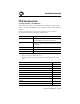
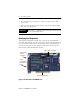
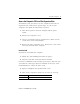
0 F 1 45 23 6 7 ABCDE PCI 2 Axis Servo Card 7 Card Identification Switch 89 LED Connection for cable (1784-PM02AE-TP0x) to Termination Panel Figure 2 Front View of the 1784-PM02AE Card Card Identification Switch The Card Identification Switch associates the 1784-PM02AE cards with slots in the virtual backplane. Each card has a specific slot identification which is listed by the backplane monitor The virtual backplane monitor assigns installed 1784-PM02AE card(s) to virtual backplane slot(s).
PCI 2 Axis Servo Card It is a slotted rotary switch with 16 switch positions – 0 through 9 and A through F. The switch is accessible by a flathead screwdriver through the PCI slot at the rear of the computer. LED There is one bi-color LED to indicate the status of the Servo card. It is visible through the PCI slot at the rear of the computer. At start up the LED goes through a sequence of color changes: • At power up LED is Green. • When SoftLogix driver starts the LED turns Red.
PCI 2 Axis Servo Card 9 Access the Computer’s PCI Local Bus Expansion Slots To install the card, you must access the computer’s PCI local bus expansion slots. Follow these general steps, or refer to your computer’s user guide for instructions on how to: 1. Turn off the power to the host computer with the power switch. 2. Remove the computer’s cover. 3. Select a vacant PCI local bus expansion slot. Make sure the vacant slot is on the main PCI Bus. 4. Remove the slot’s expansion cover.
PCI 2 Axis Servo Card If the computer then: hangs up • you probably have a memory or I/O conflict. • You should remove all other cards and try again. If you continue to experience difficulty, call Tech Support. 5. Replace the computer’s cover (after computer boots up correctly). Termination Panel The termination panel is used in conjunction with the 1784-PM02AE card to facilitate the wiring of drives and encoders for use with the card.
PCI 2 Axis Servo Card 11 P1 The connection marked P1 is for the cable from the PCI 2 Axis Servo card. It accepts a straight 68 way Mini D shielded plug with a spring latch. Through this connection the termination panel is connected to the PCI card by a 1 meter or 3 meter premade cable. The cable is shipped with the termination panel and shares its catalog number, 1784 - PM02AE-TP0x where x represents the length of the cable.
PCI 2 Axis Servo Card P3 and P4 The P3 and P4 receptacles are for wiring the axes. P3 is Axis 0 and P4 is Axis 1.
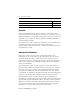
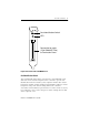
PCI 2 Axis Servo Card 13 DIN Rail Assembly The termination panel mounts to a DIN rail using the mounting feet on the back of the panel. Mounting Feet 45.
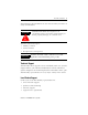
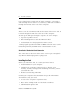
PCI 2 Axis Servo Card Cables The 1784-PM02AE card is connected to the termination panel via a premade 34 pair, 28 AWG SCSI shielded cable. The cable is available in lengths of 1 meter and 3 meters. 68 Way Connector (PX) 68 Way Connector (PY) Cable type = 34 pair, 28AWG SCSI Shielded cable 68 Way Backshell 68 Way Backshell Figure 8 1784-PM02AE-TP0x Cable Catalog Numbers for premade Servo card to termination panel cables.
PCI 2 Axis Servo Card Pin (PX) Pin Pair Number Pin Description Pin (PY) 4 Pair 4 +OUT, Axis 0 4 -OUT, Axis 0 38 DRVFLT, Axis 0 5 HOME, Axis 0 49 REG1, Axis 0 6 REG2, Axis 0 40 +ENABLE, Axis 0 7 -ENABLE, Axis 0 41 OK 1 8 IN_COM, Axis 0 42 IN_COM, Axis 0 9 IN_COM, Axis 1 43 +CH A Feedback Input Axis 1 10 - CH A Feedback Input Axis 1 44 +CH B Feedback Input Axis 1 11 -CH B Feedback Input Axis 1 45 +CH Z Feedback Input Axis 1 12 -CH Z Feedback Input Axis 1 46 +OUT, Axi
PCI 2 Axis Servo Card Sync Cable Up to four (4) 1784-PM02AE cards may be installed in a single computer provided there are enough PCI Bus slots available. A sync cable is required to keep the cards synchronized. This is a ribbon cable with four connectors that fit to the cards.
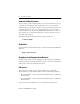
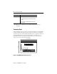
Publication 1784-IN005B-EN-P- July 2002 From 1398 Figure 10 Wiring from a 1398 to the Termination Panel Ready - Brake Reset P4 B0 B1 B2 B3 B4 B5 B6 B7 B8 B9 Brake + NC 24V 24V Com P3 B0 B1 B2 B3 B4 B5 B6 B7 B8 B9 24V Com 24V DC 24 V Com to 24V NC Reg Input Home Input NC P2 B0 B1 1398-CFLAExx Axis 1 Shield +ENABLE Ready + Estop String Reset Brake - Brake + 24V Com 24V DC 24 V Com Shield Ready - +ENABLE 24V 24V Com A0 A1 A2 A3 A4 A5 A6 A7 A8 A9 1398-CFLAExx Axis 1 1398-C
PCI 2 Axis Servo Card Card Specifications Number of Nodes 2 axes maximum Card location PCI Bus slot of PC Card keying Electronic Power dissipation 5W (1A @ 5V from PC) Encoder input Type Mode Rate Electrical interface Voltage range On state Off state Input impedance Registration inputs Type 24V input voltage Maximum Minimum on Maximum off Input impedance 24V input Response time (position latched) Incremental AB quadrature with marker 4X quadrature 4 MHz maximum Optically isolated 5V differenti
PCI 2 Axis Servo Card OK and Enable Outputs Type Operating voltage Maximum Operating current Solid-state isolated relay contacts +24V dc nominal (Class 2 source) 26.
SoftLogix is a trademark of Rockwell Automation. Windows and NT are trademarks of MicroSoft Corporation Allen-Bradley is a registered trademark of Rockwell Automation. For more information refer to our web site at: www.ab.com/motion Publication 1784-IN005B-EN-P- July 2002 Supersedes 1784-IN005A-EN-P - November 2000 95 7689-98 2002 Rockwell Automation All Rights Reserved.