
User manual


77 Publication 1747-UM011F-EN-P - May 2007
Chapter
4
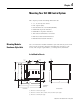
Mounting Your SLC 500 Control System
This chapter provides mounting dimensions for:
• 4, 7, 10, and 13-slot chassis.
• link coupler (AIC).
• Data Terminal Access Module (DTAM).
• DTAM Plus Operator Interface.
• DTAM Micro Operator Interface.
• AIC+ Advanced Interface Converter.
• DNI DeviceNet Network Interface.
• ENI EtherNet Network Interface.
Mounting Modular
Hardware Style Units
You can mount the modular hardware style units directly to the back
panel of your enclosure using the mounting tabs and #10 or #12
screws. The torque requirement is 3.4 Nm (30 lb-in) maximum.
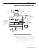
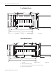
4-slot Modular Chassis
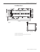
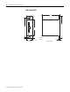
(1) Dimensions for 1746-P1 power supply.
(2) Dimensions for 1746-P2, 1746-P3, 1746-P5, 1746-P6, and 1746-P7 power supplies.
(3) Dimensions for 1746-P4 power supply.
45
(1.77)
215
(8.46)
235
(9.25)
70
(2.76)
145
(5.71)
171
(6.73)
140
(5.51)
(6.22)
171
(6.73)
140
158
11 Dia.
(0.433)
(5.51)
1.0
(0.04)
5.5 Dia.
(0.217)
5.5 Dia
(0.217)
14
(0.55)
261
(10.28)
Front View
millimeters
(inches)
Left Side View
(1)(2)(3)