
User manual


Publication 1747-UM011F-EN-P - May 2007
System Installation Recommendations 71
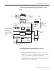
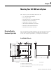
Grounded ac Power-Distribution System with Master-Control
Relay
Power Supply Required Input Voltage Characteristics
• The applied input voltage must be at or below 132V ac RMS
(265V ac RMS in 240 Volt mode).
• Minimum acceptable value of the applied input voltage must be
above 85V ac RMS (170V ac RMS in 240 Volt mode).
• The frequency of the applied voltage must be within 47...63 Hz.
• Both the positive and negative half cycles must be symmetrical
and conform to these requirements.
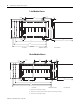
1
+–
Enclosure
Wall
Connect when
applicable
Suppressor
To Motor
Starters
Back-panel
Ground Bus
Step-down
Transformer
Grounded Conductor
Equipment-
Grounding
Conductors
Start
Suppressor
MCR
MCR
FUSE
Multiple E-stop
Switches
Controller
Power Supply
Incoming
ac
1FU
Grounding-electrode
Conductor to
Grounding-electrode
System
L1
GND
N or L2
Suppressor
Input Module
Wiring Arm
Output Module
Wiring Arm
Output
Actuator
Input
Sensor
MCR
MCR
User dc
Supply
The I/O circuits form a net
inductive load switched
by the MCR contacts.
Therefore, a suppressor is
needed across the line at
the load side of the MCR
contacts.
Disc.
2FU
3FU
L1
L2
L3
L1
L2
L3