
User manual


Publication 1747-UM011F-EN-P - May 2007
System Installation Recommendations 69
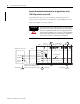
operating handle on the outside of the enclosure, so that you can
disconnect power without opening the enclosure.
Whenever any of the emergency-stop switches are opened, power to
input and output devices is stopped.
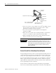
When you use the master control relay to remove power from the
external I/O circuits, power continues to be provided to the
controller’s power supply so that diagnostic indicators on the
processor can still be observed.
The master control relay is not a substitute for a disconnect to the
controller. It is intended for any situation where the operator must
quickly de-energize I/O devices only. When inspecting or installing
terminal connections, replacing output fuses, or working on
equipment within the enclosure, use the disconnect to shut off power
to the rest of the system.
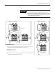
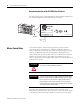
Emergency-Stop Switches
Adhere to the following points concerning emergency-stop switches.
• Do not program emergency-stop switches in the controller
program. Any emergency-stop switch should turn off all
machine power by turning off the master control relay.
• Observe all applicable local codes concerning the placement
and labeling of emergency-stop switches.
• Install emergency-stop switches and the master control relay in
your system. Make certain that relay contacts have a sufficient
rating for your application. Emergency-stop switches must be
easy to reach. See the schematic on page 71.
IMPORTANT
The operator must not control the master control relay with the
processor. Provide the operator with the safety of a direct
connection between an emergency-stop switch and the master
control relay.