
User manual


Publication 1747-UM011F-EN-P - May 2007
64 System Installation Recommendations
• Use 2.54 cm (1 in.) copper braid or 5.2 mm
2
(#10 AWG) copper
wire to connect each chassis, the enclosure, and a central
ground bus mounted on the back-panel.
• Use a steel enclosure to guard against electromagnetic
interference (EMI).
• Make sure the enclosure door viewing window is a laminated
screen or a conductive optical substrate (to block EMI).
• Install a bonding wire for electrical contact between the door
and the enclosure; do not rely on the hinge.
Connect Ground Bus to Grounding-Electrode System
The grounding-electrode system is at earth-ground potential and is the
central ground for all electrical equipment and ac power within any
facility. Use a grounding-electrode conductor to connect the ground
bus to the grounding-electrode system. Use at minimum 8.3 mm
2
(#8
AWG) copper wire for the grounding-electrode conductor to guard
against EMI. The National Electrical Code specifies safety requirements
for the grounding-electrode conductor.
Europe: Reference EN 60204 for safety information on grounding.
Also, refer to Allen-Bradley Programmable Controller Grounding and
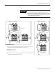
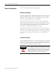
IMPORTANT
Do not lay one ground lug directly on top of the other; this type
of connection can become loose due to compression of the
metal lugs. Place the first lug between a star washer and a nut
with a captive star washer. After tightening the nut, place the
second lug between the first nut and a second nut with a
captive star washer.
Equipment Grounding Conductors
Ground Lug
Grounding-Electrode
Conductor to
Grounding-Electrode
System
Tapped Hole
Ground Bus
Ground Bus
Mounting
Bolt - Size M5 or M6 (4.826
mm or 5.48 mm) hardware
Internal star washer - Size
M5 or M6 (#10 or #12)