
User manual

Publication 1747-UM011F-EN-P - May 2007
60 System Installation Recommendations
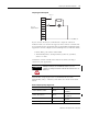
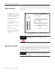
Typical Installation
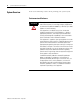
The figure below consists of some components that make up a typical
installation.
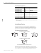
Spacing Your Controller
The figure on the following page depicts acceptable layouts. Follow
the recommended minimum spacing to allow for convection cooling
within the enclosure. Air temperature in the enclosure must be kept
within a range of 0 °C...60 °C (32 °F...140 °F).
1. NEMA-rated enclosure suitable for
your application and environment that
shields your controller from electrical
noise and airborne contaminants.
2. Disconnect device, to remove power
from the system
3. Fused isolation transformer or a
constant voltage transformer, as your
application requires
4. Master control relay/emergency-stop
circuit
5. Terminal blocks or wiring ducts
6. Suppression devices for limiting EMI
(electromagnetic interference)
generation
Disconnect
Device
Isolation
Transformer
SLC 500
Controller
MCR
(1)
(2)
(3)
(4)
(6)
(5)
ATTENTION
Vertical mounting is not recommended due to thermal
considerations.
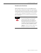
IMPORTANT
Be careful of metal chips when drilling mounting holes for the
controllers. Do not drill holes above a mounted SLC 500
controller.