
User manual


Publication 1747-UM011F-EN-P - May 2007
Calculating Heat Dissipation for the SLC 500 Control System 271
Example Heat Dissipation
Calculation
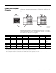
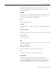
If your controller consisted of the following hardware components,
you would calculate heat dissipation as shown in the worksheet on
page 272.
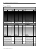
The following table details the total watts dissipated by the modules
and peripheral devices in the above SLC 500 controller. The numbers
were taken from the tables on page 267.
Chassis 2Chassis 1DTAM
Peripheral Device
User Power to
Peripheral
Slot
Slot
01 2 3 5 6 74
Chassis 1 Chassis 2
Slot Number Cat. No. Min Watts Max Watts Slot Number Cat. No. Min Watts Max Watts
0 1747-L511 1.75 1.75 4 1746-IA16 0.425 4.800
1 1746-BAS 3.750 3.80 5 1746-IA16 0.425 4.800
2 1746-IA8 0.250 2.40 6 1746-OW16 5.170
5.500
(2)
3 1746-OV8 0.675 6.90 7 1746-OW16 5.170 5.700
Peripheral
Device
1747-DTAM 2.500 2.50 NA NA NA NA
User Power to
Peripheral
NA NA NA NA NA
2.400
(1)
NA
(1)
The user power on the 1746-P1 power supply for chassis 2 is being used to power a peripheral (100 mA at 24V dc).
(2)
This output card uses 5.5 W because only 10 points are on at any one time. Using the calculated watts formula - (number of points energized x watts per point) + minimum
watts = heat dissipation of module - the calculated watts for the 1746-OW16 module is 5.5 W: (10 points x.33) + 5.17 = 5.5 W.