
User manual

Publication 1747-UM011F-EN-P - May 2007
Quick Start for Experienced Users 23
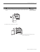
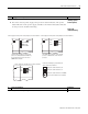
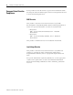
5. Wire power to the power supply. Reference
Connect incoming power.
Chapter 6
(Installing Your
Hardware
Components)
ATTENTION
Turn off incoming power before connecting wires. Failure to do so could
cause injury to personnel and/or equipment.
User Power
Incoming Power
User Power
Incoming Power
Incoming
Power
1746-P1 and 1746-P2 1746-P3
1746-P4
1746-P6
NOT USED
NOT USED
+24V dc
dc NEUT
CHASSIS GROUND
PWR OUT +24V dc
PWR OUT COM
+125V dc
dc NEUT
CHASSIS GROUND
User Power
PWR OUT +24V dc
PWR OUT COM
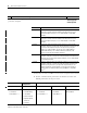
120/240V ac
V ac NEUT
CHASSIS GROUND
PWR OUT +24V dc
PWR OUT COM
85 to 132V ac
JUMPER
170 to 250V ac
L1: 85 to 132/170 to 250V ac
L2: NEUTRAL
CHASSIS GROUND
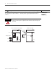
Incoming
Power
1746-P5
PWR OUT +24V dc
PWR OUT COM
+48V dc
dc NEUT
CHASSIS GROUND
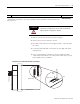
Incoming
Power
+12/24V dc
dc NEUT
CHASSIS GROUND
Incoming
Power
User Power
User Power
NOT USED
NOT USED
1746-P7
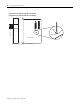
IMPORTANT
Terminal screws on the 1746-P1, 1746-P2, 1746-P3,
1746-P5, 1746-P6, and 1746-P7 power supplies
should be tightened with a maximum torque of 1 Nm
(8.8 lb-in).
Terminal screws on the 1746-P4 power supply
should be tightened with a max torque of 0.8 Nm
(7 lb-in).