
User manual


Publication 1747-UM011F-EN-P - May 2007
214 RS-232 Communication Interface
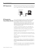
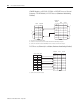
DCE Pinout
Devices such as a modem are DCE. The pinouts on these terminals
are wired to interface with DTE.
Pin Assignments for Wiring Connectors
Use the following pin assignments to wire the connectors of
Allen-Bradley control devices with modems and peripheral devices
that support RS-232 communication. See the table below to find the
wiring diagram that you need.
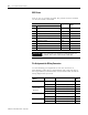
DCE 9 Pinout Signal is Equivalent DCE 25
Pinout
Pin Description
1 DCD Data Carrier Detect Input 8
2 RXD Received Data Input 3
3 TXD Transmitted Data Output 2
4 DTR Data Terminal Ready Output 20
5 COM Common Return (Signal Ground) Shared 7
6 DSR Data Set Ready Input 6
7 RTS Request to Send Output 4
8 CTS Clear to Send Input 5
9 RI Ring Indicator Input 22
IMPORTANT
DCE signal names are viewed from a DTE perspective. For
example, TXD is a DTE output and also a DCE input.
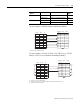
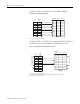
To connect this
device
To this Device Remarks See this
page
Personal computer Modem Hardware handshaking enabled 215
Peripheral DTE Hardware handshaking disabled 215
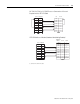
SLC 5/03, SLC 5/04,
and SLC 5/05
processors
Modem Hardware handshaking enabled 216
Peripheral DTE Hardware handshaking disabled 216
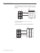
Personal Computer Using a 1747-CP3 cable 217
1747-KE module Modem Hardware handshaking enabled 217
Peripheral DTE Hardware handshaking disabled 218
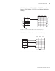
1746-BAS module Modem Hardware handshaking enabled 218
Peripheral DTE Hardware handshaking disabled 219