
User manual


Publication 1747-UM011F-EN-P - May 2007
Starting Up Your Control System 125
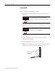
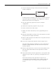
is to open the circuit at a point between the motor starter and the
relay contact.
3. Initialize and Test Your
Processor
When you are certain that machine motion cannot occur with the
controller energized, you may begin by initializing the processor using
the following steps.
1. Energize the chassis power supply. If power is supplied to the
controller and the installation is correct, the initial factory
conditions for all processors are provided in the following table.
ATTENTION
Machine motion during system checkout can be hazardous to
personnel. During the checkout procedures 3, 4, 5, and 6, you
must disconnect all devices that, when energized, might cause
machine motion.
Processor Name DEFAULT
Mode Program mode or
Fault mode
(S:1/0 to S:1/4 = 0 0001) or
(S:1/0 to S:1/4 = 0.0001 and S:1/13 = 1)
Watchdog values 100 ms S:3H = 0000 1010
I/O slot enables ALL ENABLED S:11/1 through S:12/14 set to 1
Node address
(except SLC 5/04 and 5/05)
1 Channel 1 = DH485
S:15L = 0000 0001
Communication rate
(except SLC 5/04 and 5/05)
19.2 Kbaud Channel 1 = DH485
S:15H = 0000 0100
SLC 5/03, SLC 5/04, and
SLC 5/05 processor only
Channel 0
configuration
DF1 Full-duplex
No Handshaking
19.2 KBaud
CRC Error Check
Duplicate Detect On
No Parity
SLC 5/04 processor only Channel 1
configuration
DH+
57.6 KBaud
Default Node Address = 1
SLC 5/05 processor only Channel 1
configuration
Ethernet
(1)
10 Mbps
(1)
Configuring with BOOTP enabled so that a BOOTP server on the network can automatically provide the SLC 5/05
processor with the configuration necessary to start communicating over Ethernet. See appendix G for more
information.