
User manual


Publication 1747-UM011F-EN-P - May 2007
118 Wiring Your I/O Modules
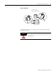
Features of an I/O Module
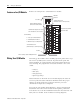
Below is an example of a combination I/O module.
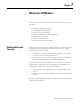
Wiring Your I/O Module
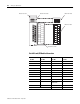
Terminals on the modules have self-lifting pressure plates that accept
two 2 mm
2
(14 AWG) wires. Series B 12-point and 16-point and
analog modules are equipped with removable terminal blocks for
ease of wiring. The plug for the removable terminals is also color
coded:
• red (ac)
• blue (dc)
• orange (relay)
• green (specialty).
Status indicators on the front of each module display the status of
each I/O point. The status indicators illuminate when the proper
signal to an input terminal is applied or when the processor
commands an output to be energized.
To locate the I/O module wiring diagrams, contact your Rockwell
Automation sales office for the latest selection guide, publication
1747-SG001. Or, locate the installation instruction sheet that was sent
with your I/O module. It also includes I/O wiring diagrams.
1
2
3
4
5
0
1
2
3
4
5
0
OUTPUT INPUT
I/O Status
Indicators
Terminal Block Screw
(maximum torque: 0.6 Nm (5.3 lb-in))
Hinged Wiring Terminal
Door with Label
Color Band
Input and Output Terminals
Connected to Terminal Block
Terminal Block (may be color-coded
and removable on some modules)
Terminal Wiring
• 2 wires per terminal maximum
• #14 AWG (2mm
2
) maximum
• Maximum torque: 0.9 Nm (8 lb-in)
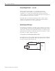
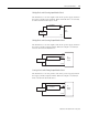
Tie Wire
Wires Leading to Input and Output Devices
Terminal Block Screw
(maximum torque: 0.6 Nm (5.3 lb-in))