Installation Instructions 17 ControlNet Scanner Card Catalog Number 1784-KTCS To the Installer This document describes how to install and use the 1784-KTCS ControlNet scanner card.
ControlNet Scanner Card If you are connecting the card directly to a ControlNet network, you also need to read: • ControlNet Tap Installation Instructions, publication 1786-5.7 • ControlNet Cable Planning and Installation Manual, publication 1786-6.2.
ControlNet Scanner Card 3 Understanding the Application Software The Allen-Bradley standard application programming interfaces (APIs) are INTERCHANGE, WINtelligent LINX, IOLinx, and RSLinx software from Rockwell Software, Inc. Contact your local Rockwell Automation sales representative or distributor for further information. Ï ÏÏ Ï Compliance to European Union Directives If this product bears the marking, it is approved for installation within the European Union and EEA regions.
ControlNet Scanner Card ATTENTION: This digital apparatus does not exceed the Class A limits for radio noise emissions from digital apparatus set out in the Radio Interference Regulations of the Canadian Department of Communications. Le présent appareil numérique n’émet pas de bruits radioélectriques dépassant les limites applicables aux appareils numériques de la class A prescrites dans le Règlement sur le brouillage radioélectrique édicté par le ministère des Communications du Canada.
ControlNet Scanner Card 5 Configuring the Card Hardware Before you install the card, you must set the card’s physical addresses for the: • ROM I/O expansion area of the host processor’s system memory—enables the card and the host computer to exchange data through the dual-port interface. This is the base memory address. • host processor’s I/O map—enables the card’s I/O devices to receive commands from the host computer. This is the base I/O space address.
ControlNet Scanner Card Selecting the Base Memory Address Location The host computer and the card exchange data via a dual-port interface. The dual-port interface is 16 Kbytes long; it begins at the specified base memory address location. The card comes set to memory address D000:0000. You may find that this selected memory address has been allocated to other interface cards or expansion memory cards you have installed in your computer system.
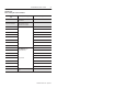
ControlNet Scanner Card 7 Worksheet A Base memory allocation worksheet Base Memory Address (hex) Host Computer Assignments 0000:0000–7000:FFFF 512K Read/Write Memory on System Board 8000:0000–9000:FFFF 128K Read/Write Memory Expansion in I/O Channel A000:0000– Video Buffer Your System A400:0000– A800:0000– AC00:0000– B000:0000– B400:0000– B800:0000– BC00:0000– C000:0000– C400:0000– Expansion Card Area (area (ar a available a ailabl for or KTCS memory addresses) C800:0000– CC00:0000– D000:0000–
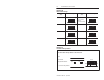
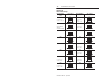
ControlNet Scanner Card Worksheet B KTCS switch settings Base Memory Addr (hex) Switch Settings C000:0000 up (1) 12 1 2 3 4 down (0) C400:0000 up (1) 12 Base Memory Addr (hex) Switch Settings D000:0000 up (1) factory set default address & recommended setting 12 D400:0000 up (1) 1 2 3 4 12 down (0) C800:0000 up (1) 12 D800:0000 up (1) 12 1 2 3 4 up (1) 12 1 2 3 4 down (0) 1 2 3 4 down (0) down (0) CC00:0000 1 2 3 4 down (0) DC00:0000 up (1) 1 2 3 4 12 down (0) 1
ControlNet Scanner Card 9 Selecting the Base I/O Space Address Location The host addresses I/O devices on the card by using their I/O space addresses. The host addresses individual devices through registers that have addresses based on the I/O space base address. The registers are 2 bytes (1 word) long. The card comes set to base I/O space address 220. You may find that this selected address has been allocated to other interface cards or expansion memory cards you have installed in your computer system.
ControlNet Scanner Card Worksheet D KTCS switch settings Base I/O Address (hex) Switch Settings 200 up (1) potential device conflict: game port 1 2 3 4 down (0) 220 up (1) factory-set default address & recommended setting 1 2 3 4 240 up (1) Base I/O Address (hex) 300 potential device conflict: prototype cards 320 potential device conflict: HDD down (0) 340 1 2 3 4 up (1) 1 2 3 4 potential device conflict: SDLC potential device conflict: EGA up (1) 1 2 3 4 potential device confli
ControlNet Scanner Card 11 Worksheet E Your base I/O space address Record the base I/O space address for the KTCS card: Card: up (1) Slot number: Using default address: yes no S3 1 2 3 4 If no, new I/O space address: down (0) Setting the Card’s Switches ATTENTION: When setting the switches, be sure to avoid touching other components on the card. 1. Follow the card handling instructions on page 4. 2. Remove the card from the anti-static clamshell.
ControlNet Scanner Card 3. If you are using the card’s default memory address setting, go to step 4. If you are setting a new base memory address, set the switches to the up or down position to reflect the selected address from Worksheet C. Front of Switches 20629–M D000:0000 Factory-set address (recommended setting) Front View up (1) S2 S1 1 2 up (1) 1 2 3 4 down (0) Publication 1784-5.
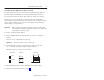
ControlNet Scanner Card 13 4. If you are using the card’s default base I/O space address setting, go to the next section, Installing the Card. If you are setting a new base I/O space address, set the switches to the up or down position to reflect the selected address from Worksheet E. Front of Switches 20629–M 220h Factory-set address (recommended setting) up (1) Front View Side View up (1) S3 1 2 3 4 down (0) down (0) Publication 1784-5.
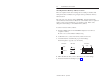
ControlNet Scanner Card Setting the Jumpers Important: When you receive your card, the jumpers are in the default positions, as shown in Figure 1. Do not alter these positions. See Figure 2 for an explanation of these jumpers. Figure 1 KTCS jumpers E2 E1 E3 20628-M Figure 2 Jumper Explanations E2 Use these jumper positions for: – normal card operation – field flash upgrade of the card’s main code E1 E2 E1 Use these jumper positions for field flash upgrade of the card’s boot code.
ControlNet Scanner Card 15 Installing the Card Important: Before you install the card, make sure you know how to configure the computer’s options, e.g., disabling cache memory, memory manager, and shadowing of memory, and that you know how to install hardware in your computer. Consult your computer’s documentation for specific information. To install the card, you need to: • access the computer’s expansion slots You need a Phillips-head or a flat-head screwdriver, depending on your system.
ControlNet Scanner Card Inserting the Card To insert the card inside the computer: 1. Follow the card handling instructions on page 4. 2. Make sure you have correctly set all of the switches on the card. 3. Insert the card into the edge connector and tighten the expansion slot screw. 4. Turn on the computer to make sure it powers up correctly.
ControlNet Scanner Card 17 Note: The CD-ROM will carry the Windows Autorun. Once inserted into the CD-ROM drive, if you have Autorun configured, the IOLinx software installation will automatically start at the first setup screen. If Autorun is not configured, go to step 2. 2. From the Start menu, choose Run. You see: 3. Type d:\setup (if it doesn’t appear automatically), where d is your CD-ROM drive letter. 4. Click OK. You see the progress bar, followed by the welcome screen. 5.
ControlNet Scanner Card 6. Enter your name, company, and product serial number. label serial number on label 7. Click Next. You see the “Choose Destination Location” screen. 8. Select from this decision table. If you want to click on install IOLinx in this directory: Next C:\Program Files\Rockwell Automation\IOLinx\ControlNet The IOLinx installation program launches the ControlNet Scanner Configuration Tool (SCT) installation.
ControlNet Scanner Card 19 9. Choose a destination location. You see the Setup progress bar, followed by the “Setup Complete” screen. 10. Check the checkboxes on the “Setup Complete” screen to choose to view the Read Me file and/or to launch the IOLinx configuration tool. The IOLinx configuration applet may be launched at a later time from the Control Panel (Start➝Settings➝Control Panel). Important: The configuration applet must be run before IOLinx is started for the first time. 11.
ControlNet Scanner Card 4. Select the I/O Base Address for this card. Refer to Worksheet E on page 11. You recorded your I/O base address there. Important: Make sure that the card is not connected to a ControlNet network. 5. Click Next to continue. The wizard prepares to locate the card at the I/O address you defined. If you have installed multiple cards, the check wizard can be run for each card by entering a different I/O address each time. 6. Click Next to continue.
ControlNet Scanner Card 21 10. Click Next to continue. The wizard prepares to reset the card, and reports Card has been reset. LEDs should be alternating green and red. Congratulations, the check wizard has verified proper configuration of your 1784-KTCS card in your computer. If the wizard fails, check the I/O base address on the card against the I/O base address you entered into the wizard.
ControlNet Scanner Card Figure 3 KTCS card connector Diagnostic status indicators Network Access Port (NAP) RJ-45 connector for connecting programming terminals to devices on a ControlNet network Channel A Redundant media BNC connectors A BNC connectors for connecting directly to a ControlNet network Channel B B 1784KTCS TIP: The light icon is channel A; the dark icon is channel B. ATTENTION: Do not use the card to connect to more than one network at a time.
ControlNet Scanner Card 23 Connecting Another Device to ControlNet Through the Network Access Port By using the card’s RJ-45 connector (known as the network access port or NAP), you can connect another device, e.g., programming interface such as a 1784-PCC card, to a ControlNet network, without a tap, through a programmable controller, I/O adapter, or another KTCS card. The 1786-CP cable (Figure 4) connects a host computer, such as one with a 1784-KTCS card, to another ControlNet device (Figure 5).
ControlNet Scanner Card Table A shows the wiring for the cable. Table A Wiring for 1786-CP connector cable Connector 1 Wire Number Signal Mnemonic Signal Name 1 ISO-GND Isolated Ground 2 N.C. No Connection 3 PTTX-H Transmit Data High 4 PTTX-L Transmit Data Low 5 PTRX-L Receive Data Low 6 PTRX-H Receive Data High 7 N.C. No Connection 8 ISO-GND Isolated Ground Connector 2 Wire Number Signal Mnemonic Signal Name 1 ISO-GND Isolated Ground 2 N.C.
ControlNet Scanner Card 25 Figure 5 Host computer connected to ControlNet device via 1786-CP cable 1784–PCC communication interface card 1784–KTCS scanner card 1786–CP cable Desktop computer Laptop computer Tap Tap Tap Tap 1794–ACN15 30433–M ATTENTION: If you connect the product to a cable system that does not support or is not using redundant media, connect the tap dropline to the BNC connector labeled channel A. Channel B is left open.
ControlNet Scanner Card Connecting the Card Directly to the ControlNet Network To connect the card directly to a ControlNet network as shown in Figure 6, follow the instructions in these publications: • ControlNet Tap Installation Instructions, publication 1786-5.7 • ControlNet Cable Planning and Installation Manual, publication 1786-6.2.
ControlNet Scanner Card 27 Table B ControlNet status interpretation • steady – indicator is on continuously in the defined state. • alternating – the two indicators alternate between the two defined states at the same time (applies to both indicators viewed together). The two indicators are always in opposite states, out of phase. • flashing – the indicator alternates between the two defined states (applies to each indicator viewed independent of the other).
ControlNet Scanner Card Removing IOLinx Software Use the Start menu or the Add/Remove control panel applet to uninstall the IOLinx software. Important: Uninstall will not succeed if the IOLinx folder is active on the desktop. You see: 1. Select from this decision table. If you want to press remove the IOLinx software Yes You see the progress bar, which indicates the percentage of files removed from your machine. retain the IOLinx files on your machine No 2. Press OK.
ControlNet Scanner Card 29 CSA Hazardous Location Approval CSA certifies products for general use as well as for use in hazardous locations. Actual CSA certification is indicated by the product label as shown below, and not by statements in any user documentation. Example of the CSA certification product label I To comply with CSA certification for use in hazardous locations, the following information becomes a part of the product literature for this CSA-certified industrial control product.
ControlNet Scanner Card Approbation d’utilisation dans des emplacements dangereux par la CSA La CSA certifie les produits d’utilisation générale aussi bien que ceux qui s’utilisent dans des emplacements dangereux. La certification CSA en vigueur est indiquée par l’étiquette du produit et non par des affirmations dans la documentation à l’usage des utilisateurs.
ControlNet Scanner Card 31 Specifications The operating parameters describe the environment within the KTCS slot. Refer to the documentation for your computer for environmental requirements. The card should not exceed those specifications.
DH+, FLEX I/O, IOLinx, PanelView, and PLC-5/40C are trademarks of Rockwell Automation. ControlNet is a trademark of ControlNet International. WINtelligent LINX and WINtelligent LINX Gateway are trademarks of Rockwell Software Inc. Ethernet is a registered trademark of Digital Equipment Corporation, Intel, and Xerox Corporation. Windows NT is a trademark of Microsoft Corporation. Worldwide representation.