Installation Instructions Stratix 2000 Ethernet Unmanaged Switch Catalog Number 1783-US8T Topic Page Important User Information 2 Environment and Enclosure 4 Before You Begin 5 Install the Switch 6 Status Indicators 13 Additional Resources 14
Stratix 2000 Ethernet Unmanaged Switch Important User Information Solid-state equipment has operational characteristics differing from those of electromechanical equipment. Safety Guidelines for the Application, Installation and Maintenance of Solid State Controls (publication SGI-1.1 available from your local Rockwell Automation sales office or online at http://www.rockwellautomation.
Stratix 2000 Ethernet Unmanaged Switch 3 North American Hazardous Location Approval The following information applies when operating this equipment in hazardous locations. Products marked "CL I, DIV 2, GP A, B, C, D" are suitable for use in Class I Division 2 Groups A, B, C, D, Hazardous Locations and nonhazardous locations only. Each product is supplied with markings on the rating nameplate indicating the hazardous location temperature code.
Stratix 2000 Ethernet Unmanaged Switch Environment and Enclosure ATTENTION: This equipment is intended for use in a Pollution Degree 2 industrial environment, in overvoltage Category II applications (as defined in IEC 60664-1), at altitudes up to 2000 m (6562 ft) without derating. This equipment is considered Group 1, Class A industrial equipment according to IEC/CISPR 11.
Stratix 2000 Ethernet Unmanaged Switch 5 About the Switch The Stratix 2000 Ethernet unmanaged switch can be used to divide an Ethernet network into segments, and to direct network traffic more efficiently than using repeating hubs. This allows for a larger network size, regardless of the amount of network traffic. Connecting one of the switch ports to a single device segments the network, letting you dedicate bandwidth to that device.
Stratix 2000 Ethernet Unmanaged Switch • To prevent the switch from overheating, observe the following minimum clearances: – Top and bottom: 50.80 mm (2 in.) – Sides: 50.80 mm (2 in.) – Front: 63.50 mm (2.50 in.) • Temperature surrounding the unit must not exceed 140 °F (60 °C).
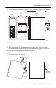
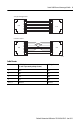
Stratix 2000 Ethernet Unmanaged Switch 7 1. Allow sufficient clearance between devices for ventilation and electrical isolation, based on the clearances listed in the Before You Begin section on page 5. 106.5 mm (4.19 in.) 53.6 mm (2.11 in.) 53.6 mm (2.11 in.) PWR 6 mm (0.24 in.) 8 5 6 3 4 1 2 35 mm (1.38 in.) 135 mm (5.31 in.) 1783-US8T 7 32312-M 2. Position the switch so that the top of the DIN rail mounting clip is slightly above the upper DIN rail edge. 3.
Stratix 2000 Ethernet Unmanaged Switch Remove the Switch from a DIN Rail 1. Gently push the switch downward to compress the mounting clip spring. 2. Rotate the bottom of the switch away from the DIN rail until the bottom of the mounting clip is clear of the lower rail. 3. Lift the switch up until the mounting clip and springs clear the upper DIN rail. Wire the Switch For simplified cabling, the switch supports automatic medium-dependent interface crossover (auto-MDIX).
Stratix 2000 Ethernet Unmanaged Switch 9 1 2 3 4 5 6 7 8 RJ45 8 7 6 5 4 3 2 1 Straight-through Cable RJ45 1 2 3 4 5 6 7 8 RJ45 8 7 6 5 4 3 2 1 Crossover Cable RJ45 32314-M Cable Pinouts Pins MDI-X Signal (+ and - represent the polarity of a wire) MDI Signal 1 RD+ TD+ 2 RD- TD- 3 TD+ RD+ 6 TD- RD- 4, 5, 7, 8 Not used Not used Rockwell Automation Publication 1783-IN010A-EN-P - June 2013
Stratix 2000 Ethernet Unmanaged Switch Connect the Power Supply WARNING: Before performing any of the following procedures, make sure power is removed from the DC circuit or the area is nonhazardous before proceeding. ATTENTION: To comply with the CE Low Voltage Directive (LVD), this equipment must be powered from a source compliant with the safety extra low voltage (SELV) or protected extra low voltage (PELV).
Stratix 2000 Ethernet Unmanaged Switch 11 Follow this procedure to connect the power supply to the switch. 1. Disconnect the power terminal connector from the switch. 2. Insert the power wires into the power terminal connector. To ensure proper polarity of the power wiring, use the cable pinout above, or the diagram on the switch label. 3. Tighten the power terminal connector by using a screwdriver. Torque must not exceed 0.5 Nm (4.42 lbin). 4. Plug the power terminal back into the device.
Stratix 2000 Ethernet Unmanaged Switch Ground the Switch The switch has two grounding points, as follows: • Functional Earth Ground (FE) in the power connector. • Protective Ground (PE) on the switch housing. PWR Connector L PWR N Functional Earth (FE) GND Protective Earth (PE) GND 32310-M ATTENTION: This product is intended to be mounted to a well-grounded mounting surface, such a metal panel.
Stratix 2000 Ethernet Unmanaged Switch 13 Apply Power to the Switch Once you apply power to the switch, if the ports are operating normally, the following happens: • The port status indicators flash for a short time. • The PWR status indicator will be on continuously.
Stratix 2000 Ethernet Unmanaged Switch Additional Resources These documents contain additional information concerning related products from Rockwell Automation. Resource Description Stratix Ethernet Managed Switches Technical Data, publication 1783-TD001 Provides specification information for the switches. Stratix 2000 Ethernet Unmanaged Switches Product Information, publication 1783-PC002 Provides system specifications and regulatory information.
Stratix 2000 Ethernet Unmanaged Switch 15 Notes: Rockwell Automation Publication 1783-IN010A-EN-P - June 2013
Rockwell Automation Support Rockwell Automation provides technical information on the Web to assist you in using its products. At http://www.rockwellautomation.com/support, you can find technical manuals, technical and application notes, sample code and links to software service packs, and a MySupport feature that you can customize to make the best use of these tools. You can also visit our Knowledgebase at http://www.rockwellautomation.