Installation Instructions Stratix 2000 Ethernet Unmanaged Switches Catalog Numbers 1783-US03T01F, 1783-US06T01F, 1783-US05T, 1783-US08T Topic Page About the Stratix 2000 Ethernet Unmanaged Switches 6 Install the Switch 10 Status Indicators 22 Specifications 24 Additional Resources 28
Stratix 2000 Ethernet Unmanaged Switches Important User Information Solid-state equipment has operational characteristics differing from those of electromechanical equipment. Safety Guidelines for the Application, Installation and Maintenance of Solid State Controls (Publication SGI-1.1 available from your local Rockwell Automation sales office or online at http://www.rockwellautomation.
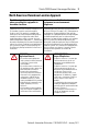
Stratix 2000 Ethernet Unmanaged Switches 3 North American Hazardous Location Approval The following information applies when operating this equipment in hazardous locations. Informations sur l’utilisation de cet équipement en environnements dangereux. Products marked "CL I, DIV 2, GP A, B, C, D" are suitable for use in Class I Division 2 Groups A, B, C, D, Hazardous Locations and nonhazardous locations only.
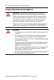
Stratix 2000 Ethernet Unmanaged Switches European Hazardous Location Approval WARNING: This equipment is intended for use in potentially explosive atmospheres as defined by European Union Directive 94/9/EC and has been found to comply with the Essential Health and Safety Requirements relating to the design and construction of Category 3 equipment intended for use in Zone 2 potentially explosive atmospheres, given in Annex II to this Directive.
Stratix 2000 Ethernet Unmanaged Switches 5 Environment and Enclosure ATTENTION: This equipment is intended for use in a Pollution Degree 2 industrial environment, in overvoltage Category II applications (as defined in IEC 60664-1), at altitudes up to 2000 m (6562 ft) without derating. This equipment is considered Group 1, Class A industrial equipment according to IEC/CISPR 11.
Stratix 2000 Ethernet Unmanaged Switches Prevent Electrostatic Discharge ATTENTION: This equipment is sensitive to electrostatic discharge, which can cause internal damage and affect normal operation. Follow these guidelines when you handle this equipment: • • • • • • Touch a grounded object to discharge potential static. Wear an approved grounding wriststrap. Do not touch connectors or pins on component boards. Do not touch circuit components inside the equipment.
Stratix 2000 Ethernet Unmanaged Switches 7 . The switches are available in the following port configurations for attaching local devices. Cat. No. Port Configuration 1783-US03T01F 3-port copper 1-port fiber 1783-US05T 5-port copper 1783-US06T01F 6-port copper 1-port fiber 1783-US08T 8-port copper The 3-port copper 1-port fiber switch (catalog number 1783-US03T01F) is shown in this publication. The individual ports autonegotiate link speeds (10 Mbps or 100 Mbps).
Stratix 2000 Ethernet Unmanaged Switches In addition to a power status indicator, each port has these indicators. • Each copper port has two link/status/activity indicators (only one of which is active at a time). • The fiber optic port has one link/status/activity indicator. When this indicator is lit Link speed is Amber (copper port only) 10 Mbps Green 100 Mbps The switches operate on low-voltage AC or DC power.
Stratix 2000 Ethernet Unmanaged Switches 9 Required Tools You need these tools to install the switch. Item Description Screwdriver 6 mm (0.25 in.) width blade 3 mm (0.12 in.
Stratix 2000 Ethernet Unmanaged Switches Install the Switch Follow these procedures to install the switch. WARNING: An electrical arc can occur: • if you connect or disconnect the communication cable with power applied to this module or any device on the network. • if you connect or disconnect wiring while the field-side power is on This can cause an explosion in hazardous location installations. Be sure that power is removed or the area is nonhazardous before proceeding.
Stratix 2000 Ethernet Unmanaged Switches 11 Make sure that the switch is oriented so that the ports face forward. The Power status indicator should be oriented to the right. See the illustrations on page 12. ATTENTION: Maintain 50 mm (2 in.) of space on the right and left sides, and the top and bottom of the switch from enclosure walls, wireways, and adjacent equipment, for ventilation and electrical isolation. . Follow these steps to mount the switch on a DIN rail. 1. Use the 6 mm (0.25 in.
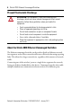
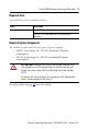
Stratix 2000 Ethernet Unmanaged Switches Product Dimensions The following illustrations show the switch dimensions. 1 2 1 P W R 2 RX L I N K 3 53 4 & TX 4 3, 4 Item Description Item - Description 1 108 mm (4.25 in.) 3 22.5 mm (0.89 in.) 2 127.8 mm (5.03 in.) 4 Other versions of the switch (not shown here, catalog numbers 1783-US06T01F and 1783-US08T) are 45 mm (1.77 in.
Stratix 2000 Ethernet Unmanaged Switches 13 Wire the Switch ATTENTION: To comply with the CE Low Voltage Directive (LVD), this equipment must be powered from a source compliant with Safety Extra Low-voltage (SELV) or Protected Extra Low Voltage (PELV). To comply with UL restrictions, this equipment must be powered from a source compliant with Class 2. Provide low-voltge AC or DC power to the switch by using the screw terminals at the top and bottom of the switch.
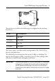
Stratix 2000 Ethernet Unmanaged Switches 5. If the connector is not already installed in the switch, wire the connector before replacing it in the switch. 1 - Item Description 1 Screw terminal connection from low-voltge AC power supply to switch 6. Use the 3 mm (0.12 in.) screwdriver to loosen the screw terminals on the connector. 7. Connect one AC output (20V AC nominal) from the low-voltge AC power supply to terminal 5 (~20) and tighten the screw. 8.
Stratix 2000 Ethernet Unmanaged Switches 15 9. Connect functional earth ground to terminal 4 and tighten the screw. IMPORTANT Maximum recommended torque for all screw connections is 0.8 N•m (7 lb•in) . Refer to the grounding considerations on page 20. 10. Plug the connector into the switch. 11. Tug gently on the wires to make sure the connections are secure. Wire the Switch for DC Operation This table shows pinouts for the DC power supply cable.
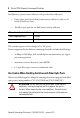
Stratix 2000 Ethernet Unmanaged Switches If the connector is not already installed in the switch (at the bottom of the switch; see item 1 below), wire the connector before replacing it in the switch. 1 $# - Item Description 1 Screw terminal connection from DC power supply to switch 5. Use the 3 mm (0.12 in.) screwdriver to loosen the screw terminals on the connector. 6. Connect DC+ (24V DC nominal) from the power supply to terminal 2 and tighten the screw. 7.
Stratix 2000 Ethernet Unmanaged Switches 17 Refer to the grounding considerations on page 20. 9. Plug the connector into the switch. 10. Tug gently on the wires to be sure the connections are secure. Connect the Copper Ethernet Ports Follow these steps to connect the copper Ethernet ports on the switch. 1. Locate the copper Ethernet RJ45 ports on the front of the switch.
Stratix 2000 Ethernet Unmanaged Switches 2. Connect one end of an Ethernet cable to one of the copper ports on the front panel of the switch. 3. Connect the other end of the Ethernet cable to a device in your Ethernet network. Connect the Fiber Optic Ethernet Port Follow these steps to connect the fiber-optic Ethernet port on the switch. ATTENTION: Do not look into the optical port. Under certain conditions, viewing the optical port may expose the eye to hazards.
Stratix 2000 Ethernet Unmanaged Switches 19 1. Locate the fiber-optic Ethernet port on the front of the switch. 1 P W R 2 TX 4 L I N K 53 4 & RX 3 1 Item Description 1 Fiber optic Ethernet ports 2. Connect the duplex LC-connector end of the fiber optic cable to the fiber-optic Ethernet port. 3. Connect the other end of the cable to a device in your network, or to another switch if connecting switches together.
Stratix 2000 Ethernet Unmanaged Switches Grounding Considerations ATTENTION: For proper grounding, you must always connect the power supply functional-ground screw when connecting the power supply. You must provide an acceptable grounding path for each device in your application. For more information on proper grounding guidelines, refer to Industrial Automation Wiring and Grounding Guidelines, publication 1770-4.1.
Stratix 2000 Ethernet Unmanaged Switches 21 1 V AC V DC 1 - Item Description 1 Connect the functional earth (FE) ground to the ground pin of either the DC (pin 1) or AC (pin 4) connector Refer to Industrial Automation Wiring and Grounding Guidelines, publication 1770-4.1, f or additional information.
Stratix 2000 Ethernet Unmanaged Switches Status Indicators To aid in troubleshooting, the switch contains these indicators: • A power indicator labeled PWR • Two-link status indicators on each copper Ethernet port (on the RJ45 connector) These indicators are not labeled on the switch faceplate. Switches with a fiber-optic Ethernet port have an additional Ethernet link-status indicator labeled LINK.
Stratix 2000 Ethernet Unmanaged Switches 23 Status Indicators Indicator Status Description PWR Solid green The switch is powered Upper copper port status indicator only Solid amber 10 Mbps Ethernet link Flashing amber There is activity on the 10 Mbps Ethernet link connected to this copper port Lower copper port status indicator only Solid green 100 Mbps Ethernet link Flashing green There is activity on the 100 Mbps Ethernet link connected to this copper port LINK Solid green An Ethernet l
Stratix 2000 Ethernet Unmanaged Switches Specifications Technical Specifications - Stratix 2000 Switches Attribute 1783-US03T01F, 1783-US06T01F, 1783-US05T, 1783-US08T Enclosure type rating Meets IP20 Inrush current, max 2.
Stratix 2000 Ethernet Unmanaged Switches 25 Technical Specifications - Stratix 2000 Switches Attribute 1783-US03T01F, 1783-US06T01F, 1783-US05T, 1783-US08T Wiring category(1) 2 - on power ports 2 - on communication ports North American temp code T4 IEC temp code T4 (1) Use this Conductor Category information for planning conductor routing. Refer to Industrial Automation Wiring and Grounding Guidelines, publication 1770-4.1.
Stratix 2000 Ethernet Unmanaged Switches Environmental Specifications - Stratix 2000 Switches Attribute 1783-US03T01F, 1783-US06T01F, 1783-US05T, 1783-US08T Operating shock • IEC 60068-2-27 (Test Ea, Unpackaged Shock) 15 g Nonoperating shock • IEC 60068-2-27 (Test Ea, Unpackaged Shock) 30 g Emissions • CISPR 11 Group 1, Class A ESD immunity • IEC 61000-4-2 1783-US06T01F: 4 kV contact discharges 8 kV air discharges 1783-US03T01F, 1783-US05T, 1783-US08T: 6 kV contact discharges 8 kV air discharges
Stratix 2000 Ethernet Unmanaged Switches 27 Certifications - Stratix 2000 Switches Certifications (when product is marked)(1) 1783-US03T01F, 1783-US06T01F, 1783-US05T, 1783-US08T c-UL-us • UL Listed Industrial Control Equipment, certified for US and Canada. See UL File E65584. • UL Listed for Class I, Division 2 Group A,B,C,D Hazardous Locations, certified for U.S. and Canada. See UL File E194810. CE European Union 2004/108/EC EMC Directive, compliant with: • EN 61326-1; Meas./Control/Lab.
Additional Resources These documents contain additional information concerning related Rockwell Automation products. Resource Description EtherNet/IP Industrial Protocol White Paper, publication ENET-WP001A Describes how to implement services and data objects on a TCP/UDP/IP based Ethernet network. Industrial Automation Wiring and Grounding Guidelines, publication 1770-4.1 Provides general guidelines for installing a Rockwell Automation industrial system. Product Certifications website, http://www.ab.