
User Manual User guide

Rockwell Automation Publication 1783-UM004E-EN-P - June 2014 65
Switch Installation Chapter 2
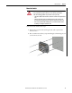
Wire External Alarms
Some switch models have the following for external alarms:
• One input alarm relay circuit to sense whether the alarm input is open or
closed relative to the alarm input reference pin.
• One output alarm relay circuit with a single Form C (single-pole,
double-throw) relay with one normally open (NO) and one normally
closed (NC) contact. You can configure the output alarm as either
normally energized or normally de-energized by using the CLI.
Refer to
Appendix C for an alarm wiring example.
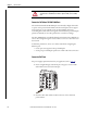
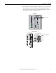
Alarm signals are connected to the switch through the 6-way alarm relay
connector. Three connections are dedicated to the alarm input.
An alarm input and the reference ground wiring connection are required to
complete a single input alarm circuit. You must provide either an NO or an NC
dry contact to complete the alarm circuit between reference ground and the
alarm input.
The three remaining connections for the Form C output alarm circuit are as
follows:
• NO output
• NC output
• common
An alarm output and the common wiring connection are required to complete a
single output alarm circuit. The Form C output alarm relay provides one NO and
one NC dry contact.
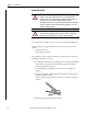
Use M12 A-coded cable to connect to the alarm connector on the switch.
Recommended torque is 0.5…0.8 N•m (4.43… 7.08 lb•in. The recommended
cable part number from Molex is 1200650523. One end of the cable has M12 A-
coded connector and the other end is open.
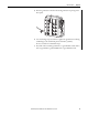
The labels for the alarm relay connector are on the switch panel.
Table 2 - Alarm Relay Connector Labels
Label Connection
NO Alarm Output Normally Open (NO) connection
COM Alarm Output Common connection
NC Alarm Output Normally Closed (NC) connection
REF Alarm Input Reference Ground connection
IN1 Alarm Input 1