
User Manual User guide

64 Rockwell Automation Publication 1783-UM004E-EN-P - June 2014
Chapter 2 Switch Installation
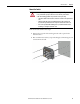
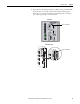
Connect the Switch to a DC Power Source
You must supply a power solution for the device. An IP67-rated cordset or
patchcord with a female-end, 4-pin mini connector is required to provide power
to the switch. Rockwell Automation offers a Bulletin 1607 IP67-rated power
supply to provide 24V DC power to the switch. Ethernet communication and
control power cables are available separately.
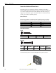
Power over Ethernet
For switches with Power over Ethernet (PoE) capability, PoE power is drawn
from the single power connection. There is no separate power input for PoE.
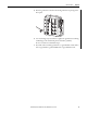
Power Cables and Cordsets
Cordsets
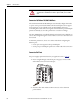
Connect the DC power to the switch through the front panel connector.
Switch Configuration Required Power Input Power Supplied per Port
PoE 44-57V 15.4 W, max
PoE+ 50-57V 30 W, max
Non-PoE 9.6…60V Not applicable
No. of Pins Assembly Rating Straight Male Right Angle Male
4 600V, 10 A 889N-M4AFC
(1)
F
(1) Replace (1) with 6 (6 ft), 12 (12 ft), or 20 (20 ft) for standard cable lengths.
Patchcords
889N-E4AFC
(1)
F
No. of
Pins
Assembly
Rating
Straight Female,
Straight Male
Straight Female,
Right Angle Male
Right Angle
Female, Straight
Male
Right Angle
Female,
Right Angle Male
4 600V, 10 A 889N-F4AFNM-
(1)
(1) Replace (1) with 1 (1 m), 2 (2 m), 5 (5 m), and 10 (10 m) for standard cable lengths.
889N-F4AFNE-
(1)
889N-R4AFNM-
(1)
889N-R4AFNE-
(1)
32475
32476
32478