
User Manual User guide

58 Rockwell Automation Publication 1783-UM004E-EN-P - June 2014
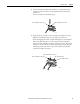
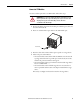
Chapter 2 Switch Installation
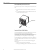
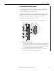
When determining where to place the switch, observe these guidelines:
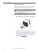
• Airflow around the switch is unrestricted. To prevent the switch from
overheating, observe the following minimum clearances:
– Top and bottom: 50.8 mm (2.0 in.)
– Sides: 50.8 mm (2.0 in.)
– Front: 50.8 mm (2.0 in.)
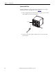
• For 10/100 ports and 10/100/1000 ports, the cable length from a switch
to an attached device cannot exceed 100 m (328 ft).
• The copper cable length from a switch to an attached device cannot exceed
the distance specified in
Appendix C.
• For maximum noise immunity, X-code shielded cables must be used on
M12 uplink ports. For recommended M12 media, refer to
http://
ab.rockwellautomation.com/Connection-Devices/EtherNet-Media.
• Temperature surrounding the unit does not exceed 60 °C (140 °F).
• Clearance to front and rear panels meets these conditions:
– Front-panel status indicators can be easily read.
– Access to ports is sufficient for unrestricted cabling.
– Front-panel direct current (DC) power connectors and the alarm relay
connector are within reach of the connection to the DC power source.
• Cabling is away from sources of electrical noise, such as radios, power lines,
and fluorescent lighting fixtures.
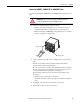
• Connect the unit to only an IP67-rated power supply. Rockwell
Automation offers a Bulletin 1607 IP67-rated power supply to provide
24V DC power to the switch.
ATTENTION: Do not wire more than 1 conductor on any single terminal.