
User Manual User guide


Rockwell Automation Publication 1783-UM004E-EN-P - June 2014 279
Cables and Connectors Appendix C
Alarm Ports
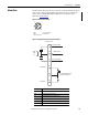
The front-panel alarm relay connector and ports are described below. The alarm
connector uses a male 5-pin DC Micro-style (M12) connector configuration
cordset, such as Allen-Bradley Bulletin 889D. For more information, see
publication
889DS-PP001.
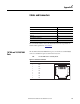
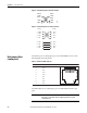
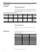
Figure 20 - Alarm Connector Pinout
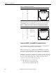
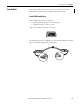
Figure 21 - Wiring Example for Alarm Inputs and Outputs
1. NO
4. Unconnected
4
5
3
1
2
2. NC
3. Unconnected
5. Common
Alarm
Relay
Coil
Alarm Input 2
Alarm Input 1
User-supplied contact closure
generates external alarms.
1
2
3
4
5
6
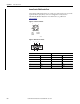
To User’s Alarm Input
+24V DC from User
To User’s Alarm Input
Alarms Connector
NO
COM
NC
IN2
REF
IN1
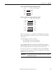
Label Connection
NO Alarm Output Normally Open (NO) connection
COM Alarm Output Common connection
NC Alarm Output Normally Closed (NC) connection
IN2 Alarm Input 2
REF Alarm Input Reference Ground connection
IN1 Alarm Input 1