
User Manual PLC-3 BACKUP CONC(OR.DU1 Owner's manual

Installing a Backup System
Chapter 2
2-13
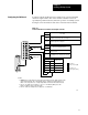
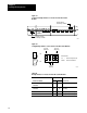
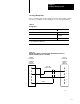
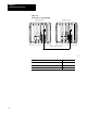
Figure 2.11
Backup
Cable W
iring for Manual Switchover (Cat. No. 1775CBB)
1
3
2
4
5
6
1
3
2
4
5
6
1775CBB
BACKUP
CABLE
SCANNER #1
BACKUP
CONNECTOR
SCANNER #1
BACKUP
CONNECTOR
PRIMARY
PROCESSOR
BACKUP
PROCESSOR
TO
SYSTEM
COMMON
SWITCH
10978I
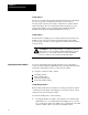
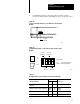
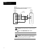
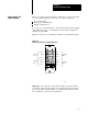
Connecting
the Backup Cable
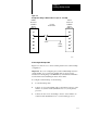
Figure 2.12 shows how to connect a backup cable for the scanner backup
configuration.
Important: If you are configuring the system for MX backup instead of
scanner backup, do not connect the backup cable as shown. See the
instructions in Configuring 1775-MX Memory Communication Modules
for information about installing the interconnect cables.
To configure scanner backup, do the following:
1. Locate the backup cable.
2. Connect one end of the backup cable to the backup connector on the
number one scanner module (thumbwheel set to 1) in the primary
processor.
3. Connect the other end to the backup connector on the number one
scanner module (thumbwheel set to 1) in the backup processor.