
User Manual PLC-3 BACKUP CONC(OR.DU1 Owner's manual

Installing a Backup System
Chapter 2
2-10
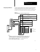
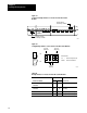
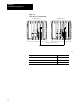
Figure 2.7
Location
of Backup Switches for 1775S5 and 1775SR5 Scanner
Modules
18754
Backup Switch at
Bottom Edge of Module
T
erminator Switch at
Bottom Edge of Module
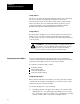
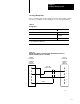
Figure 2.8
Setting
Backup Switches on 1775S5 and 1775SR5 Scanner Modules
1234
Switch Positions:
UP =
Switch is away from board
DOWN=
Switch is toward board
Not Used
(always UP)
Not Used
(always UP)
Set per
Table 2.B
ON
OFF
ON
OFF
OFF
ON
10975I
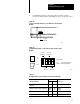
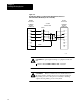
Table 2.B
Backup
Switches for 1775S5 and 1775SR5 Scanner Modules
Switch
Switchover Method 2 3 Processor
Automatic switchover with controllable
switchback
DOWN UP both primary and backup
Automatic switchover with no
switchback
DOWN
UP
UP
UP
primary
backup
Manual switchover UP DOWN both primary and backup
Standalone mode UP UP both primary and backup