
User Manual PLC-3 BACKUP CONC(OR.DU1 Owner's manual


Diagnosing Faults
Chapter 6
6-13
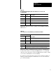
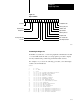
Figure 6.7
Major
Fault Bits
Stack fault
Deactive
Backup cable fault
Bad address
Bad instruction
Configuration fault
Memory parity error
Hardware fault
Major I/O fault
Watchdog timeout
Backplane fault
Bus extender fault
I/O configuration fault
17161514131211100706050403020100
11049-I
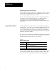
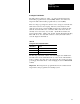
Automating
the Diagnostics
If the PLC–3 system uses a 1775–GA peripheral communication module
or a 1775–S4B scanner module, you can program a procedure to display
the major fault and the possible rung at which the fault occurred.
For example, if you used the following procedure you would display
results as shown in Table 6.J.
@FAULT
1 A = $S9:0
2 B = A .BAND. 3
3 C = $S9:2
4 IF (C/00) PR ’SYSTEM CONFIGURATION FAULT’
5 IF (C/01) PR ’MEMORY PARITY ERROR’
6 IF (C/02) PR ’HARDWARE FAULT’
7 IF (C/03) PR ’MAJOR I/O FAULT’
8 IF (C/04) PR ’WATCHDOG TIMEOUT’
9 IF (C/05) PR ’BACKPLANE FAULT’
10 IF (C/06) PR ’BUS EXTENDER FAULT’
11 IF (C/07) PR ’I/O CONFIGURATION FAULT’
12 IF (C/010) PR ’DEACTIVE’
13 IF (C/011) PR ’BACKUP CABLE FAULT’
14 IF (C/014) PR ’BAD ADDRESS’
15 IF (C/015) PR ’BAD INSTRUCTION’
16 IF (C/017) PR ’STACK FAULT’
17 IF (B .EQ. 1) PR ’DETECTED AT RUNG RM’$S9:1
18 IF (B .EQ. 2) PR ’DETECTED AT RUNG RS’$S9:1
19 IF (B .EQ. 3) PR ’DETECTED AT RUNG RF’$S9:1
20 IF (C .EQ. 0) PR ’NO FAULT DETECTED’