
User Manual PLC-3 BACKUP CONC(OR.DU1 Owner's manual


Diagnosing Faults
Chapter 6
6-7
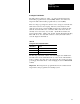
Table 6.E
Data
Highway/Data Highway Plus Status Indicators for 1775S5, SR5
Scanner Modules
Indicator Status Description
XMTG ON transmitting a message
RCVG ON receiving a message
RDY ON ready to transmit a message
ERR ON programming or communication error detected
DIS ON Data Highway/Data Highway Plus channel is disabled
Important: When the scanner is polling, both the XMTG and RCVG
LEDs turn on.
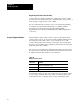
Table 6.F
Status
Indicators for 1775MX Memory Communication Modules
Indicator & Status
PRI B/U
Description
ON OFF Processor in primary mode
OFF ON Processor in backup mode
OFF OFF Processor faulted
ERR
ON Communication error detected between two memory communication modules
OFF Communication normal between two memory communication modules
Whenever possible, communication between memory communication
modules will continue even though the ERR indicator is on. If the MX
status area of the data table is created, the ERR indicator remains on until
you reset the communication error bit (S4:0/07).
If you have not created the status section, the error indicator remains on
until the problem causing the communication error is corrected, then it
goes off automatically.