Chapter 1 PLC 3 Programmable Controller Backup Systems User Manual
Important User Information Because of the variety of uses for this product and because of the differences between solid-state products and electromechanical products, those responsible for applying and using this product must satisfy themselves as to the acceptability of each application and use of this product. For more information, refer to publication SGI-1.1 (Safety Guidelines for the Application, Installation and Maintenance of Solid-State Control).
Table of Contents Preface . . . . . . . . . . . . . . . . . . . . . . . . . . . . . . . . . . . . . . . P 1 Manual Objectives . . . . . . . . . . . . . . . . . . . . . . . . . . . . . . . . . . . Audience . . . . . . . . . . . . . . . . . . . . . . . . . . . . . . . . . . . . . . . . . . What This Manual Contains . . . . . . . . . . . . . . . . . . . . . . . . . . . . WARNINGS, CAUTIONS and Important Information . . . . . . . . . . . Terms and Conventions . . . . . . . . . . . . . . . . . . . . . . . . .
ii Table of Contents Programming Techniques . . . . . . . . . . . . . . . . . . . . . . . . . 5 1 Chapter Objectives . . . . . . . . . . . . . . . . . . . . . . . . . . . . . . . . . . . Signal Conditioning . . . . . . . . . . . . . . . . . . . . . . . . . . . . . . . . . . Timers and Counters at Switchover . . . . . . . . . . . . . . . . . . . . . . . Timing Considerations at Switchover . . . . . . . . . . . . . . . . . . . . . . Forcing I/O . . . . . . . . . . . . . . . . . . . . . . . . . . . . . . .
Preface Preface Manual Objectives This manual shows you how to install, configure, and operate a backup system configured with PLC-3 or PLC-3/10 processors. In this manual we describe: backup system concepts procedures for installing backup systems procedures for operating backup systems programming techniques fault diagnosis Audience Before you read this manual or attempt to use a backup system, you should be familiar with the PLC-3 or PLC-3/10 programmable controller.
Preface WARNINGS, CAUTIONS and Important Information Information that is especially important to note is identified by three labels: WARNING CAUTION Important WARNING: tells you of circumstances or practices that can lead to personal injury as well as damage to equipment. CAUTION: tells you of circumstances or practices that can lead to damage of equipment. Important: provides you with information that is important for the successful application of the PLC-3 backup system.
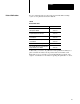
Preface Related Publications For more information about components used with the PLC-3 backup system, see the publications listed in Table B. Table B Related Publications Publication Title Publication Number PLC 3 Programmable Controller Installation and Operation Manual 1775 6.7.1 PLC 3 Family Programmable Controller Programming Reference Manual 1775 6.4.1 I/O Scanner Programmer Interface Module User's Manual 1775 6.5.2 PLC 3 Communication Adapter Module User's Manual 1775 6.5.
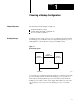
Chapter 1 Choosing a Backup Configuration Chapter Objectives The information in this chapter can help you: understand backup concepts evaluate different backup configurations choose a switchover method Backup Concepts A backup system consists of two processors configured in such a way that the backup processor will take control of outputs if the primary processor faults. Figure 1.1 shows the basic concept of a backup system. Figure 1.
Chapter 1 Choosing a Backup Configuration Why Use a Backup System? Backup is useful for applications in which an unexpected shutdown is costly or otherwise undesirable. By configuring a PLC-3 or PLC-3/10 system for backup communication, you can guard against shutdowns caused by processor faults. Shutdowns can also be caused by power losses or faults in equipment other than the programmable controller. For these cases, you must take other measures to guard against shutdown.
Chapter 1 Choosing a Backup Configuration Primary processor - the processor that is controlling outputs. When switchover to the backup processor occurs, the backup processor becomes the primary processor, since now it is controlling outputs. Stand-alone processor - a programmable controller that is not configured for backup. Switchover - transfer of control from the primary processor to the backup processor.
Chapter 1 Choosing a Backup Configuration Choosing a Backup Configuration There are two backup configurations: scanner backup (Figure 1.2) which uses only I/O scanner modules MX backup (Figure 1.3) which uses 1775-MX memory communication modules How Scanner Backup Works Figure 1.2 shows the implementation of scanner backup. The number one scanner module controls switchover as well as backup, peer-to-peer, and I/O communication channels. Figure 1.
Chapter 1 Choosing a Backup Configuration How MX Backup Works Figure 1.3 shows the implementation of MX backup. The scanner modules still control I/O communication channels but the memory communication modules handle data transfers between the primary and backup processors. Figure 1.
Chapter 1 Choosing a Backup Configuration Selecting Scanner or MX Backup Table 1.A and Table 1.B summarize the attributes of scanner backup and MX backup, respectively. Choose the backup configuration most suitable for your application. Table 1.A Scanner Backup Attributes Advantages: Disadvantages: No additional cost (every 1775 S4A, SR, S5, and SR5 has this feature built in).
Chapter 1 Choosing a Backup Configuration Choosing a Switchover Method The three methods of switching control of outputs from the primary to the backup processor are: automatic switchover with no switchback automatic switchover with controllable switchback manual switchover You can use any one of these methods for scanner backup, but you must use automatic switchover with controllable switchback for MX backup. Table 1.C lists the attributes associated with each method. Table 1.
Chapter 1 Choosing a Backup Configuration Switchover Method: Attributes: Manual Switchover When the primary processor faults, the system shuts down as though no backup system were available. Operator intervention is required at switchover. Control of the process is lost until switchover occurs. Quickly resume control of a process following a fault in the primary processor. Easy to transfer between primary and backup processor.
Chapter 2 Installing a Backup System Chapter Objectives This chapter describes how to install PLC-3 and PLC-3/10 backup systems. Specifically, it provides recommendations for: power supplies grounding shielding configuring I/O chassis configuring scanner modules connecting I/O channel wiring configuring memory communication modules Installing the Hardware In general, the recommendations and procedures for installing a PLC-3 or PLC-3/10 backup system closely resemble those of a stand-alone processor.
Chapter 2 Installing a Backup System Important: The number one scanner module (thumbwheel set to 1) in both primary and backup processors must be a 1775-S4A or -S5 for PLC-3 based processors, or a 1775-SR or -SR5 for PLC-3/10 based processors. Figure 2.1 on page 2-3 shows typical connections for a PLC-3 backup system using scanner backup. Figure 2.2 on page 2-4 shows typical connections for a PLC-3 backup system using MX backup. Figure 2.
Chapter 2 Installing a Backup System Figure 2.1 Connections for a PLC 3 Backup System Using Scanner Backup 1 2 9 2 12 8 5 3 To Earth Ground 10 7 5 13 2 3 11 7 4 4 6 To other I/O Chassis in the Channel 6 Blue 8 7 Shield 7 Clear 1. 2. 3. 4. 5. 6. 7. 8. 9. 10. 11. 12. 13. PLC-3 Processor (Primary) Power Supply (cat. no. 1775-P1) 1771 I/O Chassis (cat. no. 1771-A1B, -A2B, A3B, -A4B) Power Supply (cat. no. 1771-P2) Processor Chassis Power Cable, 6ft. (cat. no.
Chapter 2 Installing a Backup System Figure 2.2 Connections for a PLC 3 Backup System Using MX Backup 1 2 9 2 12 8 5 3 To Earth Ground 10 7 5 13 2 3 11 7 4 4 6 To other I/O Chassis in the Channel 6 Blue 8 7 Shield 7 Clear 1. 2. 3. 4. 5. 6. 7. 8. 9. 10. 11. 12. 13. PLC-3 Processor (Primary) Power Supply (cat. no. 1775-P1) 1771 I/O Chassis (cat. no. 1771-A1B, -A2B, A3B, -A4B) Power Supply (cat. no. 1771-P2) Processor Chassis Power Cable, 6ft. (cat. no.
Chapter 2 Installing a Backup System Figure 2.3 Connections for a PLC 3/10 Backup System Using Scanner Backup 1 7 10 6 To Earth Ground 8 5 2 2 9 5 3 3 4 To other I/O Chassis in the Channel 4 Blue 6 5 Shield 5 Clear 1. 2. 3. 4. 5. 6. 7. 8. 9. 10. PLC-3/10 Processor (Primary) 1771 I/O Chassis (cat. no. 1771-A1B, -A2B, A3B, -A4B) Power Supply (cat. no. 1771-P2) I/O Power Cable, 1ft. (cat. no. 1771-CE) Twinaxial Cable (cat. no. 1770-CD) 10,000 ft. Max. Each I/O Channel at 57.
Chapter 2 Installing a Backup System Power Supply Considerations For a PLC-3 backup system, it is important to choose suitable power supplies and make sure they are connected properly. To reduce the chance of inadvertent shutdowns due to loss of power, we recommend using two separate 1775-P1 or -P3 power supplies. Use one power supply for the primary processor and the other power supply for the backup processor. Further, connect each power supply to a separate source of AC power.
Chapter 2 Installing a Backup System Configuring the I/O Chassis You must configure all I/O chassis for backup mode operation. Each I/O chassis has eight switches. Two of the switches, switches 2 and 8, are especially important because they affect the operation of a backup system. See Figure 2.4 for the function and location of the I/O chassis switches. Figure 2.
Chapter 2 Installing a Backup System Setting Switch 2 The processor restart lockout switch (switch 2) must be ON so the backup processor is capable of restarting the I/O chassis at switchover, if necessary. If the system has more than one I/O chassis, switch 2 must be ON in each chassis. For more detailed information about the processor restart lockout feature, refer to the PLC-3 Programmable Controller Installation and Operations Manual (publication 1775-6.7.1).
Chapter 2 Installing a Backup System 2. Set all backup switches on all other scanner modules, if any are present, in both the primary and backup processors to the up position. Figure 2.5 Location of Backup Switches for 1775 S4A and 1775 SR Scanner Modules Top Edge of Module 18753 Figure 2.
Chapter 2 Installing a Backup System Figure 2.7 Location of Backup Switches for 1775 S5 and 1775 SR5 Scanner Modules Backup Switch at Bottom Edge of Module Terminator Switch at Bottom Edge of Module 18754 Figure 2.8 Setting Backup Switches on 1775 S5 and 1775 SR5 Scanner Modules Not Used (always UP) ON Not Used (always UP) ON OFF Switch Positions: ON UP = Switch is away from board DOWN = Switch is toward board OFF 1 2 3 4 OFF Set per Table 2.B 10975 I Table 2.
Chapter 2 Installing a Backup System Selecting a Backup Cable Choose a backup cable for the switchover method desired. Table 2.C lists the choices. See Figure 2.9 through Figure 2.11 for wiring information. Table 2.C Backup Cables Switchover Method: Backup Cable: Automatic switchover with no switchback 1775 CBA Automatic switchover with controllable switchback 1775 CBB1 1775 CM2 Manual switchover 1775 CBB 1. Use for scanner backup configuration. 2. Use for MX backup configuration. Figure 2.
Chapter 2 Installing a Backup System Figure 2.10 Backup Cable Wiring for Scanner Backup with Automatic Switchover with Controllable Switchback (Cat. No.
Chapter 2 Installing a Backup System Figure 2.11 Backup Cable Wiring for Manual Switchover (Cat. No. 1775 CBB) PRIMARY PROCESSOR BACKUP PROCESSOR 1775 CBB BACKUP CABLE SCANNER #1 BACKUP CONNECTOR SCANNER #1 BACKUP CONNECTOR 1 1 2 2 3 3 4 4 SWITCH TO SYSTEM COMMON 5 6 5 6 10978 I Connecting the Backup Cable Figure 2.12 shows how to connect a backup cable for the scanner backup configuration.
Chapter 2 Installing a Backup System Figure 2.
Chapter 2 Installing a Backup System Connecting the I/O Channel Wiring There are four I/O serial communication channels per scanner. Depending on your system architecture, you can use one or more of them for: I/O communication Peer-to-peer communication Backup communication To do this, you connect I/O cables to the terminal swing arm and configure each channel for the type of communication desired. You configure I/O channels by using LIST. Figure 2.
Chapter 2 Installing a Backup System Connecting I/O Communication Channels Figure 2.14 shows the connections when using I/O channel 1. Figure 2.14 Connections for I/O Communication Primary Processor Backup Processor Blue Blue Shield Twinaxial Cable (cat. no. 1770-CD) Terminator (cat. no. 1770-XT) (Refer to page 2 23) Shield To I/O Chassis Clear Channel No. 1 Shown Clear Channel No.
Chapter 2 Installing a Backup System If you designate another I/O channel for use as an I/O communication channel, replace the references to I/O channel 1 with the actual I/O channel in the following procedure. 1. Connect one end of a 1770-CD twinaxial cable (Belden 9463) to the I/O channel 1 terminals on the terminal swing arm of a scanner module in the backup processor. 2.
Chapter 2 Installing a Backup System Connecting an I/O Channel for Peer to Peer Communication Any I/O channel can be used for peer-to-peer communication. Figure 2.15 shows the connections when using I/O channel 1. Figure 2.15 Connecting an I/O Channel for Peer to Peer Communication Primary Processor Backup Processor Terminator (cat. no. 1770-XT) (Refer to page 2 23) Blue Twinaxial Cable (cat. no. 1770-CD) Shield Blue Shield To other PLC-3 systems Clear Channel No. 1 Shown Clear Channel No.
Chapter 2 Installing a Backup System If you designate another I/O channel for use as a peer-to-peer communication channel, replace the references to I/O channel 1 with the actual I/O channel used in the following procedure. 1. Connect one end of a cat. no. 1770-CD twinaxial cable to the I/O channel 1 terminals on the terminal swing arm of a scanner module in the backup processor. If this is a 1775-S4A or 1775-SR scanner module, do not connect the shield.
Chapter 2 Installing a Backup System 8. If the last scanner is a 1775-S4A or 1775-SR scanner module, install a 1770-XT terminator to the I/O channel 1 terminals as shown in Figure 2.15. For 1775-S5 and 1775-SR5 scanner modules, you can either install a 1770-XT terminator or select a terminator by using the internal switches as shown in Figure 2.17 on page 2-23. 9. Using the LIST function, configure I/O channel 1 in the backup processor for peer-to-peer communication.
Chapter 2 Installing a Backup System Connecting an I/O Channel for Backup Communication Any I/O channel can be used for backup communication. Figure 2.16 shows the connections when using I/O channel 1. Figure 2.16 Connecting an I/O Channel for Backup Communication Primary Processor Backup Processor Terminator (cat. no. 1770-XT) Blue Blue Twinaxial Cable (cat. no. 1770-CD) Shield (Refer to page 2 23) Shield Terminator (cat. no. 1770-XT) Clear Channel No.
Chapter 2 Installing a Backup System If you designate another I/O channel for use as a backup communication channel, replace the references to I/O channel 1 with the actual I/O channel used in the following procedure. 1. Connect one end of a 1770-CD twinaxial cable to the I/O channel 1 terminals on the terminal swing arm of a scanner module in the backup processor. 2.
Chapter 2 Installing a Backup System Terminators The first and last physical device of each I/O channel requires a terminator. Use discrete terminators (cat. no. 1770-XT) for 1775-S4A, -SR scanner modules. The 1775-S5, -SR5 scanner modules have internal terminators that can be enabled/disabled with a switch. See Figure 2.17 and Figure 2.7. Figure 2.
Chapter 2 Installing a Backup System Configuring 1775 MX Memory Communication Modules To implement MX backup you need two 1775-MX memory communication modules, one for the primary processor and another for the backup processor, and one 1775-CM memory communication cable assembly. The cable assembly consists of four cables. Two of them are interconnect cables (3 feet long) that eliminate the need for a 1775-CBA or 1775-CBB backup cable. The other two cables are communication cables (30 feet long).
Chapter 2 Installing a Backup System To configure MX backup, do the following: 1. Insert one memory communication module in the primary processor and one in the backup processor. A memory communication module can occupy any slot in a PLC-3 processor chassis; however, to obtain the best system performance in multi-chassis systems, you should place the memory communication module in the same chassis as the memory modules. 2.
Chapter 3 Operating a Backup System Chapter Objectives This chapter describes how to operate a backup system. It recommends procedures for: starting up a backup system shutting down a backup system restarting a backup system disconnecting a faulted processor restarting a repaired processor. CAUTION: To guard against damage to equipment, make sure you follow the startup procedure recommended for your backup system configuration.
Chapter 3 Operating a Backup System Startup Procedure Method 1 1. Turn off both the primary and backup processors, if they are not already off. 2. Turn on the backup processor. 3. Select program load mode in the backup processor. 4. Load the program into the backup processor. 5. Select automatic configuration to configure the I/O channels in the backup processor. 6. Manually configure peer-to-peer or backup communication channels, if any are used.
Chapter 3 Operating a Backup System Startup Procedure Method 2 1. Turn off both the primary and backup processors, if they are not already off. 2. Turn on the primary processor. Important: Whichever processor you turn on first is designated as the primary processor; the other is designated as the backup processor. 3. Select program load mode in the primary processor. 4. Load the program into the primary processor. 5.
Chapter 3 Operating a Backup System Figure 3.1 Example Rung for Performing Memory Download at Startup Inputs B1:0 S0:3 EN 00 17 Shutting Down a Backup System Restarting a Backup System 3-4 MSG Message Control Channel Download #B0:0 E2.14.1 05 DN ER To shut down a backup system, do the following: 1. Select program load mode in the primary processor. 2. Select program load mode in the backup processor. 3. Turn off the backup processor. 4. Turn off the primary processor.
Chapter 3 Operating a Backup System Disconnecting a Faulted Processor To troubleshoot and/or repair a faulted processor, you may have to disconnect it. To disconnect a faulted processor, do the following: 1. Turn off the faulted processor. 2. Disconnect the following cables: 3. a. For the scanner backup configuration, disconnect the backup cable from the number one scanner module in the faulted processor. b.
Chapter 3 Operating a Backup System Restart Procedure Method 1 1. Turn off both processors, if they are not already off. 2. Reconnect the backup cable to the number one scanner module in the repaired processor. 3. Reconnect the terminal swing arms to all scanner modules in the repaired processor. 4. Turn on the backup processor. 5. Select program load mode in the backup processor. 6. Verify that channel configurations, values in data tables, and user program are correct in the backup processor.
Chapter 3 Operating a Backup System Restart Procedure Method 2 1. For the scanner backup configuration, place the switch, located in the backup cable, so that the processor currently controlling outputs is the primary processor. 2. Reconnect the following cables: a. For scanner backup configuration, reconnect the backup cable to the number one scanner module in the repaired processor. b.
Chapter 4 Using the 1775 MX Memory Communication Module Chapter Objectives This chapter describes how to use 1775-MX memory communication modules. Depending on your application, you can program the memory communication module to: transfer data from the primary processor to the backup processor to ensure that the data table in the backup processor matches that in the primary processor. transfer data from the backup processor to the primary processor to provide data or status back to the primary.
Chapter 4 Using the 1775 MX Memory Communication Module Controlling the Operation of Memory Communication Modules As shown in Table 4.A, you can control operation of memory communication modules by using: LIST functions (see page 4-3). message (MSG) instructions (see page 4-16). Typically, you use LIST functions during the development of your application. This approach lets you select and deselect options manually.
Chapter 4 Using the 1775 MX Memory Communication Module The following sections describe how to control memory communication modules by using LIST functions and message instructions. Using LIST Functions for Control The LIST functions for memory communication modules follow the same convention as other modules in a PLC-3 system.
Chapter 4 Using the 1775 MX Memory Communication Module Figure 4.1 LIST Menu for Primary and Backup Processor SYSTEM MODE 1 TEST MONITOR 2 * RUN MONITOR 3 PROGRAM LOAD 4 * REMOTE ENABLE 5 SYSTEM STATUS 6 MODULE STATUS ENTER NEXT > MODULES 1 01 1775-ME8 A/A 2 01 1775-L3 A/E 3 01 1775-S5 A/G 4 01 1775-MX A/C ENTER NEXT > MCM OPERATION CHASSIS 00 SLOT 06 SYSTEM ID.
Chapter 4 Using the 1775 MX Memory Communication Module As shown in Table 4.B, a heading, which appears directly beneath the system identification, identifies the current source of control commands for the memory communication module. Table 4.
Chapter 4 Using the 1775 MX Memory Communication Module The MCM OPERATION menu contains an entry for each LIST function listed in Table 4.D. These functions are a subset of those available when using message instructions. Table 4.D LIST Functions Command Description INACTIVE The memory communication module stops both continuous data transfers and continuous file transfers to the backup processor.
Chapter 4 Using the 1775 MX Memory Communication Module Inactive Command The INACTIVE command lets you discontinue continuous data table and file transfers. As long as the selection INACTIVE is active, the memory communication module inhibits data and file transfers between the primary processor and the backup processor. If a data or file transfer was in progress when you selected the INACTIVE function, it will become effective on completion of the transfer in progress.
Chapter 4 Using the 1775 MX Memory Communication Module File Selection Command To specify a group of files, select the entry FILE SELECTION in the MCM OPERATION menu. The files currently in the list are displayed, followed by the prompt FILE SELECTION ENTER NEXT>. You select up to 16 files, one at a time, by entering information using the following syntax: e/sf [ENTER] where: e is the entry number (1 to 16) s is the data table section specifier (Table 4.E) f is the file number Table 4.
Chapter 4 Using the 1775 MX Memory Communication Module Important: Timers and counters cannot be separated into control, preset, and accumulated value for the purpose of file transfers. In addition, pointers cannot be separated into section, file, and word. Therefore, no file number is necessary (although you can specify file 0).
Chapter 4 Using the 1775 MX Memory Communication Module Data Table Transfer Command The DATA TABLE XFER command lets you transfer all of the data table sections except the status section (section 13), from the primary processor to the backup processor continuously. The memory communication module transfers all undefined sections, i.e., 14, 15, and so on, as well. The primary processor must be in run mode or test mode for transfers to occur.
Chapter 4 Using the 1775 MX Memory Communication Module Memory Download Command The MEMORY DOWNLOAD command lets you transfer the entire contents of the PLC-3 memory from the primary to the backup processor. This transfer occurs once each time you request it, and has a higher priority than the data transfer function. The backup processor cannot take control of outputs if the primary processor faults during the download.
Chapter 4 Using the 1775 MX Memory Communication Module When you select the LOCK SYSTEM command, the memory communication module attempts to acquire the edit resource for both the primary and backup processors. The edit resource is defined as the ability of a programming terminal to create and/or edit the ladder program in the current context and manipulate the data table.
Chapter 4 Using the 1775 MX Memory Communication Module Enable Program Compare Command The ENABLE PROG COMP command lets you compare the ladder program in the backup processor with the one in the primary processor on a word-by-word basis. This function works in conjunction with the program compare limits selections. See Table 4.F. Table 4.F Program Compare If the memory communication module: Then: completes the program compare without error bit 13 is set in file 4, word 0 of the status section.
Chapter 4 Using the 1775 MX Memory Communication Module Disable Program Compare Command The DISABLE PROG COMP command lets you disable the program comparison function. When this command is active, the memory communication module resets the program comparison status bit. Program Compare Limits Command The PROG COMP LIMITS command lets you select specific sections of the ladder program to be compared when ENABLE PROG COMP has been selected.
Chapter 4 Using the 1775 MX Memory Communication Module To enter the program compare limits, do the following: 1. Select the command PROG COMP LIMITS from the MCM OPERATION menu by typing: 10 [ENTER] 2. Enter the program limits into the PROG COMP LIMITS menu using the following syntax: m/s/f where: 3.
Chapter 4 Using the 1775 MX Memory Communication Module Backup to Primary Data Transfer Command The BACKUP TO PRIMARY DATA TRANSFER command lets you enable the backup to primary data transfer function. When enabling or disabling this feature, the processor must be in program mode.
Chapter 4 Using the 1775 MX Memory Communication Module Using Message Instructions for Control Operation of a memory communication module using message (MSG) instructions follows the same convention as other modules in a PLC-3 system. The memory communication module has additional functions, however, that let you enable and disable operation of memory communication modules from the ladder program. Table 4.G lists the commands available for use in message instructions.
Chapter 4 Using the 1775 MX Memory Communication Module Command Abbreviation Description ENABLE COMPARE EC The memory communication module compares a specified section of the ladder program in the backup processor with the corresponding section in the primary processor on a word by word basis. DISABLE COMPARE DI C The memory communication module prevents the execution of the program compare function.
Chapter 4 Using the 1775 MX Memory Communication Module See Table 4.H when creating a message instruction: Table 4.H Message Instruction Components Enter the: Which is: Control section and starting word of the control file. (The control file is usually a binary file; and, binary files must start at word 0.) Channel always the address E2.14.
Chapter 4 Using the 1775 MX Memory Communication Module Start $ Command The START $ command lets you transfer selected files from the primary to the backup processor. You can select from 1 to 16 files for use with this function. The START $ function is equivalent to the FILE TRANSFER function in LIST.
Chapter 4 Using the 1775 MX Memory Communication Module Table 4.I Data Table Section Specifiers Data Table Selection Specifier Output Image O Input Image I Timer T Counter C Integer N Floating Point F Decimal (BCD) D Binary B ASCII A High Order Integer H Pointers P Status S Important: Timers and counters cannot be separated into control, preset, and accumulated value for the purpose of file transfers. In addition, pointers cannot be separated into section, file, and word.
Chapter 4 Using the 1775 MX Memory Communication Module Figure 4.3 Example Rung Illustrating Continuous File Transfer | B1:0 | +––] +–(EN)–+ | 00 | | | | | | | | | | | | | S0:3 +MSG–––––––––––––––––––––––––+ [–––] [–––––––––––––––––––––––––––––––+MESSAGE 17 |Control |Channel #B0:0| E2.14.1+–(DN) |START $N2, T | | +–(ER) | | | | +––––––––––––––––––––––––––––+ Bit B1:0/00 is an internal storage bit used to control execution of the transfer command.
Chapter 4 Using the 1775 MX Memory Communication Module Transfer $ Command The TRANSFER $ command lets you transfer selected files from the primary processor to the backup processor one time. You can select from 1 to 16 files for use with this function. The TRANSFER $ command and START $ command are quite similar.
Chapter 4 Using the 1775 MX Memory Communication Module Start Data Command The START DATA command lets you transfer the entire contents of the data table, except the status section, from the primary processor to the backup processor. The START DATA function is equivalent to the DATA TABLE XFER function in LIST.
Chapter 4 Using the 1775 MX Memory Communication Module Transfer Data Command The TRANSFER DATA command lets you transfer all sections of the data table, except the status section, from the primary processor to the backup processor one time only. The transfer includes all sections of the data table except the status section (section 13). The TRANSFER DATA command and the START DATA commands are quite similar.
Chapter 4 Using the 1775 MX Memory Communication Module Important: A memory download will not occur if: - the backup processor has insufficient memory to accommodate the memory contents of the primary processor. Should this occur, the memory communication module will abort the memory download function and resume operation. - an error occurs during download. In this case, the memory communication module aborts the memory download function and the backup processor shuts down.
Chapter 4 Using the 1775 MX Memory Communication Module You can check the status of each processor by looking at file 4, word 0 of the status section. For further information about interpreting status words refer to Using Data Table Status Bits in chapter 5. Important: The PLC-3 backup system is not considered locked unless the edit resource is acquired for both processors. When the PLC-3 backup system is locked, a programming terminal cannot edit the ladder program in the current context.
Chapter 4 Using the 1775 MX Memory Communication Module Table 4.J Enable Compare If the memory communication module: Then: completes the program compare without error bit 13 is set in file 4, word 0 of the status section. (You must reset this bit.) The memory communication module continues the comparison until a miscompare occurs.
Chapter 4 Using the 1775 MX Memory Communication Module For example, if the primary processor encountered a message instruction containing the command: ENABLE COMPARE 1/2/0 (assuming the proper label comment numbers exist in the sections of the ladder program) the memory communication module would: compare the section in the main routine of the ladder programs starting at the first rung and ending at the rung containing the label with comment number 1.
Chapter 4 Using the 1775 MX Memory Communication Module Disable Outputs Command The DISABLE OUTPUTS command lets you inhibit the backup processor from taking control of outputs when the primary processor faults. This command is useful during an on-line editing session in an application where control of the outputs by the backup processor after switchover is undesirable while the programs are different.
Chapter 4 Using the 1775 MX Memory Communication Module List Control Command The LIST CONTROL command lets you redirect control of a memory communication module from the ladder program to LIST. Only the primary processor can execute the LIST CONTROL command. After the primary processor executes a message instruction containing the LIST CONTROL command, operation of the memory communication module will be controlled by selections in LIST.
Chapter 4 Using the 1775 MX Memory Communication Module Status On Command The STATUS ON command lets you enable data transfer from the backup processor to the primary processor. When the primary processor executes a message instruction containing the STATUS ON command, the backup processor transmits up to sixteen words from the data table status section (beginning at S4:4) of the memory communication module into corresponding data table locations of the memory communication module in the primary processor.
Chapter 4 Using the 1775 MX Memory Communication Module Error Codes Table 4.K is a list of error codes. These error codes may appear while you are controlling the operation of a memory communication module through message instructions from a ladder program. Table 4.K Program Control Error Codes Error Code Description 1 Unknown command 2 Ambiguous command Syntax errors that can 3 Invalid compare limits be detected when the 4 Unknown object instruction is enabled.
Chapter 4 Using the 1775 MX Memory Communication Module If an error occurs, check the following: If the backup processor is powered down or faulted due to a memory error, communication between memory communication modules will be interrupted until the backup processor is functional again. A broken communication cable between memory communication modules will cause both the primary and backup processors to fault.
Chapter 5 Programming Techniques Chapter Objectives This chapter describes techniques you can use to program a PLC-3 backup system.
Chapter 5 Programming Techniques Using Repetition to Handle Short Input Pulses One method of handling short input pulses is to repeat the rungs that read those inputs. For example, if the duration of an input pulse is only 70% of the recommended time, you could repeat rungs depending on this input at least twice in the program. Put approximately one third of the program between the rungs.
Chapter 5 Programming Techniques Timing Considerations at Switchover When using PLC-3 processors in a backup system configuration, program scans are not synchronized; and, although switchover is fast (approximately 100 milliseconds), it is not instantaneous. Therefore, it is possible that the primary and backup processors could read different input conditions during a particular scan.
Chapter 5 Programming Techniques If the start pushbutton is pressed for too short a time, the input change may be seen by the primary processor but not by the backup processor. Should this occur, bit O3/0 would be set in the backup processor one program scan later than in the primary processor (because input I2/2 from the auxiliary contact would be set and energize output O3/0).
Chapter 5 Programming Techniques Forcing I/O The force table is not transferred from the primary to the backup processor over any communication channel. Thus, if forces have been set in the primary processor, they will not be transferred to the backup processor. If switchover occurs, the backup processor will become active but no forces will be set. To prevent this undesirable situation, we suggest that you set the forces first in the primary processor and then in the backup processor.
Chapter 5 Programming Techniques Reducing Backup Communication Overhead A PLC-3 backup system using memory communication modules requires the least amount of communication overhead. Data is transferred quickly and efficiently from the memory communication module in the primary processor to its partner in the backup processor over a dedicated parallel communication link.
Chapter 5 Programming Techniques Figure 5.3 Programming for Block Transfer Inputs | Run/ BTR | | Backup Done | | S0:3 B200:12 +BTR––––––––––––––––––––+ | +––] [––––]/[–––––––––––––––––––––––––––––––––––+BLOCK TRANSFER READ +–(EN)–+ | 17 15 |Rack 12| | | |Group 7+–(DN) | | |Module 1| | | |Control #B200:12+–(ER) | | |Data file #D110:0| | | |Length 64| | | +–––––––––––––––––––––––+ | . . .
Chapter 5 Programming Techniques +––––––––––––––––––––––––––––––––––––––––––––––––––––––––––––––––––––––––(MCR)– + | | Other Program Rungs 10982 I 5-8
Chapter 5 Programming Techniques Another approach for reducing the amount of data transferred across a backup communication channel is to use Data Highway or Data Highway Plus communication. Although you will still need a backup communication channel to provide protection against having both processors controlling outputs at the same time, you can use a Data Highway or Data Highway Plus port as an additional backup communication channel.
Chapter 5 Programming Techniques Backed up/Not backed up Bit The backed-up/not-backed-up bit (file 0, word 3, bit 16) is set when option switch 2 on the number one scanner module is in the down position. The status of this bit is influenced by the switchover configuration.
Chapter 5 Programming Techniques The checksum is stored in file 0, word 5 and the checksum done bit is stored in file 0, word 4, bit 17 of the data table status section. The done bit is set when the checksum operation is completed. It remains set until reset manually or cleared automatically by the application program. Figure 5.4 shows one use of the checksum. In this example, the status value is compared to a known good value, which you previously stored in file 0, word 1 of the binary section.
Chapter 5 Programming Techniques Refer to the PLC-3 Family Programmable Controller Programming Reference Manual (publication 1775-6.4.1) for detailed information regarding the data table status section.
Chapter 5 Programming Techniques 1775 MX Module Communication If the PLC-3 backup system uses memory communication modules, there are additional bits in the data table status section (file 4, word 0) to indicate communication status between memory communication modules. Status information for the memory communication module resides in file 4, words 0, 1, and 2 of the data table status section.
Chapter 5 Programming Techniques Important: Upon completing the program compare function, the memory communication module sets either bit 12 or 13 in status file 4, word 0, to show the condition of the transferred data. You must reset these bits before checking the status of the next program compare function. Table 5.B Status File 4, Word 0 in the Data Table Bit: Meaning: 00 On when the backup processor is in the run mode. 01 On when the backup processor is in the test mode.
Chapter 5 Programming Techniques Figure 5.
Chapter 5 Programming Techniques 1775 MX Module Backup to Primary Transfer Data Words In response to the BACKUP TO PRIMARY DATA TRANSFER in LIST or the STATUS ON command from a message instruction, up to 16 words are sent from the backup system to the primary system. The backup system transmits a maximum of 16 words from the MX data table status area beginning at S4:4 into the corresponding data table status locations in the primary system.
Chapter 5 Programming Techniques Series A, Revision D (or later) 1775 KA Modules When using series A, revision D (or later) communication adapter modules, you can either follow the guidelines previously described for early communication adapter modules or select backup operation with the LIST function. Important: Do not select backup operation for multidrop modem applications because the modem port is not disabled after a processor fault.
Chapter 5 Programming Techniques As long as the primary processor is controlling outputs, the station address of the communication adapter module in the backup processor is modified as shown in Table 5.C. Table 5.C Data Highway Station Numbers for 1775 KA Modules If the station address is between: The backup module assumes a station address that is: 0008 and 2768 1008 higher than the station address assigned to the communication adapter module in the primary processor.
Chapter 5 Programming Techniques When you select backup, you assign the same Data Highway or Data Highway Plus station number to both the scanner module in the primary processor and the one in the backup processor. As long as the primary processor is controlling the outputs, the station address of the Data Highway or Data Highway Plus channel in the backup processor is modified. Table 5.E and Table 5.F show the station number modifications for Data Highway and Data Highway Plus, respectively.
Chapter 5 Programming Techniques When you do not select backup, you assign a unique Data Highway (0008 to 3768) or Data Highway Plus (008 to 778) station number to the scanner module in the primary processor and the one in the backup processor. The backup will continue to operate with the same station number even after the switchover. WARNING: To guard against personal injury and damage to equipment, do not assign the same station number to both scanner modules, if you have not selected backup mode.
Chapter 5 Programming Techniques Figure 5.7 Sending a Message at Switchover | B1:0 | +––] +–(EN)–+ | 00 | | | | | | | | | | | | | S0:3 +MSG–––––––––––––––––––––––––+ [–––] [–––––––––––––––––––––––––––––––+MESSAGE 17 |Control |Channel #B200:1| E2.5.1+–(DN) |#H045$N4:17=$B3:5 | | +–(ER) | | | | +––––––––––––––––––––––––––––+ Bit B1:0/00 is an internal storage bit used to control execution of the transfer command. You can use any unused data table bit for this purpose.
Chapter 5 Programming Techniques Programming Considerations for Memory Communication Modules another station on the Data Highway is initiating a message possibly neither of the processors will respond to the message. You must program the other station to respond to this condition. another station is communicating with the primary processor the other station will receive no indication that switchover has occurred.
Chapter 5 Programming Techniques for the primary and backup processors. Then, place executable instructions above the rung and disallowed instructions below the rung. Figure 5.
Chapter 6 Diagnosing Faults Chapter Objectives This chapter describes how to diagnose faults in a PLC-3 backup system using: status indicators on the front panels of processors and on the front panels of modules in the processors system status words. Also, it describes a simple diagnostic technique that can help you identify the program section and rung number of faults when they occur. Before discussing fault diagnosis, however, you should review what happens when a processor encounters a major fault.
Chapter 6 Diagnosing Faults Now the backup processor is controlling outputs. If the backup processor attempts to execute the same logic rung that caused the primary processor to shut down, the backup processor will: display the message DEACTIVE on the front panel of the backup processor if a 1775-S4A or -SR is scanner number one; or display the major fault on the front panel of the backup processor if a 1775-S5 or -SR5 is scanner number one.
Chapter 6 Diagnosing Faults Figure 6.1 Processor Front Panel PROCESSOR OUTPUTS PROGRAM ACCESS 10921 Table 6.
Chapter 6 Diagnosing Faults Table 6.
Chapter 6 Diagnosing Faults Figure 6.2 Indicator Locations for 1775 S4 and 1775 SR Scanner Modules 1775 - SR Scanner 1775 - S4A Scanner PASS and FAIL indicators Thumbwheel switch I/O channel status indicators 18750 Figure 6.
Chapter 6 Diagnosing Faults Figure 6.4 Indicator Locations for 1775 MX Memory Communication Module 1775 - MX Scanner PASS and FAIL indicators Status indicators 18752 Table 6.D I/O Channel Indicators for All Scanner Modules Indicator CHx Configured for I/O Scanning CHx Configured for peer to peer communication CHx Configured for backup communication Status ON Communication between scanner module and the I/O chassis on the corresponding I/O channel is properly established.
Chapter 6 Diagnosing Faults Table 6.E Data Highway/Data Highway Plus Status Indicators for 1775 S5, SR5 Scanner Modules Indicator Status Description XMTG ON transmitting a message RCVG ON receiving a message RDY ON ready to transmit a message ERR ON programming or communication error detected DIS ON Data Highway/Data Highway Plus channel is disabled Important: When the scanner is polling, both the XMTG and RCVG LEDs turn on. Table 6.
Chapter 6 Diagnosing Faults Diagnosing Faults with Status Word Bits Another method of diagnosing faults is to examine the contents of status words in the system memory. The state of individual bits, groups of bits, or both can help you pinpoint the source of faults. For more information about status words, see the chapter Programming Considerations in this manual.
Chapter 6 Diagnosing Faults Creating the Fault Routine The fault routine requires two rungs; one rung as the first rung in the main ladder program memory section (RM0) and the other as the first rung in the fault routine ladder program memory section (RF0). These two rungs copy diagnostic status words to storage words in the data table status section for safe keeping until they can be analyzed.
Chapter 6 Diagnosing Faults Figure 6.
Chapter 6 Diagnosing Faults | | | +–––––––––––––––––––––+ 10988 I 6-11
Chapter 6 Diagnosing Faults Keep the following points in mind when you use the fault routine in your ladder program. the rung in the main routine must be executed in both the primary and backup processors you must make certain that the set value in the watchdog timer configuration is large enough to include the execution of this fault routine along with the normal program scan. any logic which follows the RET instruction in the fault routine section will not be executed.
Chapter 6 Diagnosing Faults Figure 6.
Chapter 6 Diagnosing Faults Table 6.
With offices in major cities worldwide WORLD HEADQUARTERS Allen-Bradley 1201 South Second Street Milwaukee, WI 53204 USA Tel: (414) 382-2000 Telex: 43 11 016 FAX: (414) 382-4444 EUROPE/MIDDLE EAST/AFRICA HEADQUARTERS Allen-Bradley Europa B.V. Amsterdamseweg 15 1422 AC Uithoorn The Netherlands Tel: (31) 2975/60611 Telex: (844) 18042 FAX: (31) 2975/60222 Publication 1775–6.3.1 — November 1991 Supersedes publication 1771–6.3.