Allen Bradley PLC-3 Communication Adapter Module (Cat. No.
Table of Contents Introduction . . . . . . . . . . . . . . . . . . . . . . . . . . . . . . . . . . . . 1 1 General . . . . . . . . . . . . . . . . . . . . . . . . . . . . . . . . . . . . . . . . . . . About This Manual . . . . . . . . . . . . . . . . . . . . . . . . . . . . . . . . . . . Module Description . . . . . . . . . . . . . . . . . . . . . . . . . . . . . . . . . . Specifications . . . . . . . . . . . . . . . . . . . . . . . . . . . . . . . . . . . . . . Applications . . . . . . . . . . . . . . .
ii Table of Contents Message Procedure Commands . . . . . . . . . . . . . . . . . . . . 6 1 General . . . . . . . . . . . . . . . . . . . . . . . . . . . . . . . . . . . . . . . . . . . Assignment Command . . . . . . . . . . . . . . . . . . . . . . . . . . . . . . . . CREATE Command . . . . . . . . . . . . . . . . . . . . . . . . . . . . . . . . . . DELETE Command . . . . . . . . . . . . . . . . . . . . . . . . . . . . . . . . . . Execute . . . . . . . . . . . . . . . . . . . . . . . . . . . . . . . . .
Table of Contents iii The Network and Application Layer Protocol . . . . . . . . . . . 12 1 Network Layer . . . . . . . . . . . . . . . . . . . . . . . . . . . . . . . . . . . . . . Application Layer . . . . . . . . . . . . . . . . . . . . . . . . . . . . . . . . . . . . 12 1 12 6 Message Formats . . . . . . . . . . . . . . . . . . . . . . . . . . . . . . . A 1 Introduction . . . . . . . . . . . . . . . . . . . . . . . . . . . . . . . . . . . . . . . . Basic Command Set . . . . . . . . . . . . . . .
Chapter 1 Introduction General About This Manual The PLC–3 Communication Adapter Module (cat. no. 1775–KA) is an optional module used in the PLC–3 main chassis or expander chassis. It serves two purposes: 1. Interfacing the PLC–3 processor with the Allen–Bradley Data Highway 2. Interfacing the PLC–3 processor with an intelligent RS–232–C device This manual describes the installation, programming, and operation of the 1775– KA module.
Chapter 1 Introduction Chapter 10 – describes how to write a full–duplex line driver to enable a computer to communicate to the 1775–KA’s RS–232–C channel. Chapter 11 – describes how to write a half duplex line driver to enable a computer to communicate to the 1775–KA’s RS–232–C channel. Chapter 12 – describes the network and application layers of a software driver to enable a computer to communicate to the 1775–KA’s RS–232–C channel. Appendix A – shows detailed message formats.
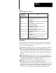
Chapter 1 Introduction Table 1.B Related Data Highway Documentation Publication Number (Old/New No.) Title 1770-810/1770-6.2.1 Data Highway Cable Assembly and Installation Manual 1771-801/1771-6.5.1 Communication Adapter Module (cat. no. 1771-KA) User's Manual 1771-802--------- Communication Controller Module (cat. no.1771-KC/KD) User's Manual 1771-811/1771-6.5.8 PLC-2 Family/RS-232C Interface Module (cat.no. 1771-KG) User's Manual 1771/822/1771-6.5.
Chapter 1 Introduction command is sometimes used synonymously to mean privileged command. non–privileged commands include any command that both PC’s and RS–232–C device can send. The non–privileged commands include the protected write and unprotected read and write commands. The non–privileged commands are also referred to as “PLC/PLC–2 type” commands. Module Description Figure 1.1 illustrates the front of the 1775–KA module.
Chapter 1 Introduction Figure 1.1 Communication Adapter Module (Cat. No.
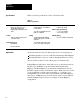
Chapter 1 Introduction Specifications Table 1.C lists the specifications for the 1775–KA module. Table 1.C Module Specifications Function Location Interface the PLC-3 Processor with the Allen-Bradley Data Highway and/or with an RS-232-C device Single slot in PLC-3 main chassis or expander chassis Communication Ports Data Highway Communication Rate To Data Highway - 57.6 kilobaud recommended To modem-programmable from 110 baud to 19.
Chapter 1 Introduction Figure 1.
Chapter 1 Introduction The PLC–3 can support multiple 1775–KA modules in the same PLC–3 chassis. This provides the PLC–3 with concurrent access to several independent Data Highways. The 1775–KA module can also serve as an interface between the PLC–3 programmable controller and an intelligent RS–232–C compatible device or any Allen–Bradley PC and its Data Highway module.
Chapter 2 Installation General This chapter describes installation of the 1775–KA module in two phases: Installing hardware Programming configuration parameters through the PLC–3 LIST function Please read the entire manual carefully before attempting to install the module. Hardware Installation For best results when installing the 1775–KA module, proceed in the order indicated below.
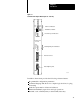
Chapter 2 Installation Figure 2.1 Front View of 1775-KA Module PASS FAIL SELF TEST NO KA XMTG RCVG ERR DIS MODEM INTERFACE Self–Test Indicators Thumbwheel Switch RS–232–C port Indicators COMMUNICATION ADAPTER XMTG RCVG RDY ERR DIS DATA HWY Data Highway Port Indicators RS–232–C Port Data Highway Port DATA HWY 10003-I If there is only one 1775–KA module in the PLC–3 chassis, set its thumbwheel switch to the number 1.
Chapter 2 Installation CAUTION: To guard against unpredictable operation of the PLC–3 processor, do not change the setting on any thumbwheel switch while the 1775–KA module is powered–up. Option Switches Figure 2.2 shows a set of four option switches on the bottom edge of the 1775– KA module. Switches 1 and 2 are used when the PLC–3 controller is programmed to operate in a backup configuration.
Chapter 2 Installation Table 2.A 1775-KA Switch Settings If this switch: Is: 1 OPEN Then the PLC will switch over to backup whenever one of the following fault conditions occurs: 1. The 1775-KA module tries to hold control of the PLC-3 backplane for more than 138 microseconds. 2. The 1775-KA module experiences a execution timeout of more than 32 milliseconds 3. The 1775-KA module experiences an internal stack overflow 4. The 1775-KA module experiences severe Data Highway communication problems.
Chapter 2 Installation Indicators There are three sets of LED indicators on the front of the 1775–KA module (Figure 2.1). The first group, labeled SELF–TEST, indicates the result of internal diagnostic tests that the module continuously performs on its own hardware and firmware. The second group, labeled MODEM INTERFACE, indicates the status of communication through the module’s RS–232–C port. The last group, labeled DATA HWY, indicates the status of communication through the module’s Data Highway port.
Chapter 2 Installation Data Highway Cable Connections There are two cable connectors, or ports, on the front of the 1775–KA module (Figure 2.1). The bottom port, labeled DATA HWY., is for connection to the Allen–Bradley Data Highway. If you are using the 1775–KA module in a Data Highway application, plug the Data Highway dropline cable into this port. For details on the installation of the Data Highway cable, refer to the Data Highway Cable Assembly and Installation Manual (publication 1770–810).
Chapter 2 Installation Interfacing a PLC–3 controller with a computer, either directly or through modems (Figure 2.4) Figure 2.
Chapter 2 Installation Interfacing a PLC–3 controller with a remote Data Highway through a modem link (Figure 2.5) Figure 2.
Chapter 2 Installation Interfacing a PLC–3 controller to a PLC–2 Family processor through a 1771–KG module in a point–to–point link (Figure 2.6) Figure 2.6 Linking a PLC-3 to PLC-2 Family Controller PLC–3 Controller Modem 1775–KA Module PLC–2 Controller Modem 1771–KG Module NOTE: Modems required only for distances greater than 50 feet.
Chapter 2 Installation Interfacing a PLC–3 controller as a slave station on a multipoint modem link (Figure 2.7) Figure 2.7 Linking a PLC-3 to a Multi-drop Modem Link Computer Multidrop Modem Master Station Multidrop Modem Link PLC-3 Controller Modem 1775-KA Module 10008–I Slave Stations The first four applications above use the module’s RS–232–C port in the unpolled mode, while the last application uses the polled mode.
Chapter 2 Installation Each mode of operation requires a different communication protocol. The unpolled mode uses full–duplex protocol (chapter 10) while the polled mode uses half–duplex protocol (chapter 11). In general, full–duplex protocol gives faster data throughput but is more difficult to implement; half–duplex protocol is easier to implement but gives slow data throughput.
Chapter 2 Installation Table 2.C Distance Rate Variations Distance in feet Maximum Baud Rate 1,000 19,200 2,000 9,600 3,000 9,600 4,000 4,800 5,000 4,800 6,000 2,400 7,000 2,400 The receiver is designed to sense the signal generated by a similar transmitter, and is electrically isolated from all other circuitry on the module. It consists of an opto–isolater circuit with an input and return connection at the RS–232 connector.
Chapter 2 Installation Pinout The necessary RS–232–C port connections are described in Table 2.D below: Table 2.
Chapter 2 Installation sequence. Some modem will not respond to DTR until the phone rings, while others will always pick up the phone whether it is ringing or not. DSR (data set ready) is a signal from the modem to the RS–232 connector that the phone is off–hook. (It is the modem’s answer to DTR). The module will not transmit or receive unless DSR is true. If the modem does not properly control DSR, or if no modem is used, DSR must be jumpered to an RS–232 high signal at the RS–232 connector.
Chapter 2 Installation Figure 2.8 Connection to Allen-Bradley 1771-KG or 1771-KE/KF Module Connect the Shield at One End Only 1 RS–232–C CHANNEL Connector of 1775–KA Module 1 1 2 3 7 13 3 2 25 14 4 4 5 5 6 6 8 8 20 11 2 RS–232–C CHANNEL Connector of 1771–KG or 1771–KE/KF Module 1 Conductors 2 and 7, 3 and 25 must be twisted pairs for distances longer than 50 feet. 2 Set switch 3 (on the 1775–KA) OFF when the module is communicating with another Allen-Bradley device.
Chapter 2 Installation Figure 2.9 Connection to Allen-Bradley 1775-KA Module Connect the Shield at One End Only 1 RS–232–C CHANNEL Connector of 1775–KA Module 2 1 1 2 3 7 25 3 2 25 7 4 4 5 5 6 6 8 8 20 20 RS–232–C CHANNEL Connector of 1771–KA Module 1 Conductors 2 and 7, 3 and 25 must be twisted pairs for distances longer than 50 feet. 2 Set switch 3 (on the 1775–KA) OFF when the module is communicating with another Allen-Bradley device.
Chapter 2 Installation Figure 2.10 Connection to user-Supplied Modem or RS-232-C Device RS–232–C 1 CHANNEL Connector of 1775–KA Module 1 Protective Ground 1 Transmitted Data 2 Received Data 3 Request to Send 4 Clear to Send 5 Data Set Ready 6 Signal Ground 7 Line Signal Detect 8 Data Terminal Ready 20 Received Data Return 25 Set Switch 3 ON to ground pin 25. User–supplied Moderm or RS–232–C Device 10011–I Private lines are permanently connected phone lines used with modems.
Chapter 2 Installation DTR, DSR, and DCD signals. It incorporates timeouts and tests to properly operate these types of modems. Auto–answer: these modems have self–contained timeouts and tests, and can answer and hangup the phone automatically. The modem port has no means to control an auto–dial modem, although it is possible that it can be used in conjunction with a separate auto–dialer. Answering The module continually asserts DTR when it is waiting for a call.
Chapter 2 Installation The transmission format may be summarized as follows: start bit data bit 0 data bit 1 data bit 2 data bit 3 data bit 4 data bit 5 data bit 6 data bit 7 even parity bit (optional) one stop bit The 1775–KA module selects baud and parity through the LIST function (section titled Programmable Configuration Parameters). Programmable Configuration Parameters A number of installation parameters for the 1775–KA module can be programmed through the PLC–3 LIST function.
Chapter 2 Installation Figure 2.
Chapter 2 Installation You access the LIST function by typing the word LIST and press the ENTER key. After accessing the LIST function, select option 6 MODULE STATUS from the SYSTEM–MODE MENU. LIST then presents you with a menu that describes the modules in your system. The menu varies according to the modules in your PLC–3.
Chapter 2 Installation 3 ACCEPT UPLOAD/DOWNLOAD 4 ACCEPT WRITES 5 BACKUP OPERATION 6 PLC–2 MASK ENTER NEXT> This menu allows you to select options that apply equally to both the modem port and the Data Highway port of the 1775–KA module. These options are described below. Timeout The timeout is the maximum amount of time that the 1775–KA module will wait for another station to reply to one of its messages. The allowed entries are 0 to 9999, expressed in increments of 1/10 second.
Chapter 2 Installation Send Unprotected This option determines whether or not the 1775–KA module will be able to send unprotected command messages to other stations. If you select option 2 SEND UNPROTECTED, the 1775–KA module will be able to send both protected and unprotected commands. You can use an unprotected command to read or write to any area of a PC data table. You can use a protected command, however, to write only to those areas of a PC data table specified by the PC that receives the command.
Chapter 2 Installation keyswitch is on. At initial power–up, the module enables the ACCEPT WRITES option by default. Backup Operation This option determines whether or not a pair of 1775–KA modules will provide backup for each other. Enable option 5 (BACKUP OPERATION) for both the primary and backup 1775–KA modules to enable backup operation as described in section 2.3 (backup configurations). If you make no selection for option 5, backup operation is disabled by default.
Chapter 2 Installation This menu allows you to select options that apply to only the Data Highway port of the 1775–KA module. These options are described below. Enable/Disable Port This option determines whether or not the 1775–KA module can communicate over the Data Highway. you must select the ENABLE option in order to allow communication to take place. If you make no selection, the PLC–3 disables this port by default.
Chapter 2 Installation 5 EVEN PARITY 6 SEND EMBEDDED RESPONSES ENTER NEXT> This menu allows you to select options that apply to only the modem port of the 1775–KA module. These options are described below. Enable/Disable Port This option determines whether or not the 1775–KA module can communicate through its RS–232–C port. You must select the ENABLE option in order to allow this communication to take place. If you make no selection, the PLC–3 disables the RS–232–C port by default.
Chapter 2 Installation Communication Mode This option determines whether the RS–232–C port of the 1775–KA module can operate in a half–duplex (polled) or full–duplex (unpolled) mode. Select full– duplex for point–to–point communication through the RS–232–C port. Select half–duplex if the 1775–KA module is installed as a slave station on a multipoint modem link. If you make no selection, the 1775–KA selects the full– duplex (unpolled) mode by default.
Chapter 2 Installation module must have its own unique station number. If you want to send the same message through both 1775– KA modules, you must program the two separate message instructions. The second configuration provides system backup for the PLC–3 controller. If the 1775–KA modules are Rev. C or earlier, you: 1. Assign different station addresses to each communication adapter module. 2.
Chapter 2 Installation 2. Use the LIST function to disable the modem and Data Highway ports. 3. Use the LIST function to select BACKUP OPERATION for both the primary and backup 1775–KA modules. For more information, see the PLC–3 Installation and Operation manual (publication 1775–6.7.1). Thus, when you select BACKUP OPERATION, the condition appears like this: 5*BACKUP OPERATION 4.
Chapter 2 Installation Figure 2.12 How addresses of the primary and backup PLC-3 controllers change during switchover.
Chapter 2 Installation Using Manual Switchover After you select the BACKUP OPERATION for a rev. D. (or later) 1775–KA module, you may choose to use your PLC–3 backup system for manual switchover. In manual switchover, you must initiate the switchover by changing the position of a switch in a backup cable. (Refer to the PLC–3 Programmable Controller Backup Concepts Manual, pub. 1775–803, for more details.) You must be sure to turn off the faulted PLC–3 processor before you begin the switchover, however.
Chapter 2 Installation Figure 2.13 Example of a Rung that Sends a Message during switchover from primary PLC-3 to backup PLC-3. MSG 1 MESSAGE TYPE CTL = FB200:00001 = 0 CHANNEL: E2.5. #H045$N4:17= $B3:5 E0000 00 E0000 S0003 01 STAT DN 15 STAT ER 13 E0000 00 17 E0000 L 01 E0000 00 S0003 17 STAT EN 12 NOTE: Bits E0000/00 and E0000/01 are internal storage bits. You can use any unused data table section to reference these bits. Bit S0003/17 is the run/backup bit.
Chapter 2 Installation If an automatic switchover occurs: And: Then: the PLC-3 processor is waiting for a response the response is ignored another station on the Data Highway is initiating a message possibly neither of the PLC-3 processors will respond to the message. You must program other stations on the Data Highway to recover from this condition another station is communicating with the primary PCL-3 processor the other station will receive no indication that a switchover has occurred.
Chapter 3 Data Highway Communication General This chapter introduces some of the concepts and terminology involved with operating the 1775–KA module of the Data Highway. Some Terminology The Allen Bradley Data Highway is a communication network for industrial control applications. The Data Highway consists of a central trunkline cable that may be up to 10,000 feet long. This cable can link together as many as 64 distinct communication points (or nodes) called stations.
Chapter 3 Data Highway Communication A command message either gives (writes) data to, or requests (reads) data from, one station to another. A reply message is a station’s response to a command message. Command messages are generated by message procedures that you program into the 1775–KA module. Execution of a message procedure is controlled by the message (MSG) instruction in the PLC–3 ladder diagram program.
Chapter 3 Data Highway Communication To enter a message instruction, complete the steps below: 1. Enter a condition that, when true, will activate the message instruction. In Figure 3.1, we used an examine–on for input word 00128, bit 01. Figure 3.1 Levels of Programming in Data Highway Communication 1) PLC–3 Processor 2) 1775–KA Module Ladder Diagram Program MSG 10012 01 Data Highway Message Procedure PROC_A STAT EN 12 MESSAGE TYPE 1 CTL = FB200:0000=200 CHANNEL: E2.5.
Chapter 3 Data Highway Communication 2. Press the message instruction key. 3. Specify message type 1. 4. Choose a control file word where status information about the message command can be stored. In our Figure 3.1, we used binary file 200, word 200. Data transfers can be either solicited or unsolicited, depending on whether they are initiated by the local or a remote station, respectively. Either type of station initiates the data transfer by issuing a command message.
Chapter 3 Data Highway Communication When the rung becomes true, the message instruction begins sending command(s) across the Data Highway. At the same time, bits in a control file word change their state (Table 3.B) to reflect the status of the command. Even if the rung becomes false, the message command will continue to send commands across the highway. Table 3.
Chapter 3 Data Highway Communication Data Transfers The whole purpose of Data Highway communication is to transfer data from one station processor memory location to another. To accomplish these data transfers, you can program the assignment command into the 1775–KA module. Chapter 6 gives the details of the assignment command. For now, let’s just look at the simple example in Figure 3.2. In this example, the assignment command copies a word (16 bits) of data from the source to the destination location.
Chapter 3 Data Highway Communication Figure 3.3 Two Ways to Use 1775-KA Commands 2) as part of a message procedure 1) as a single command in a PLC–3 message instruction Message Procedure PROC_A MSG 10012 01 MESSAGE TYPE 1 CTL = FB200:0000=200 CHANNEL: E2.5.1 $B45:21=$112:33 STAT EN 12 (other commands) STAT DN 15 $B45:21 = $112:33 STAT ER 13 (other commands) PLC–3 Message Instruction to Control Execution of Procedure PROC_A MSG 10012 01 MESSAGE TYPE 1 CTL = BW200:0000=200 CHANNEL: E2.5.
Chapter 3 Data Highway Communication Access privileges Not every Data Highway station can read or write to every other station. In general, read and write access privileges depend on two factors: type of processor at the transmitting and receiving stations protections set at the receiving station The rest of this section explains how these access privileges vary according to the above factors. PLC–3 Stations A PLC–3 station can always read data from any major area of another PLC–3’s memory.
Chapter 3 Data Highway Communication A PLC–3 station can read from any part of a PLC/PLC–2 data table. However, A PLC– 3 station cannot write to a PLC/PLC–2 if the switch settings at the PLC/PLC–2 station forbid access. If the switches at the PLC/PLC–2 station are set to accept only protected write commands, then the ladder diagram program at the PLC/PLC–2 station must contain memory access rungs to define which areas of the PLC/PLC–2 station’s data table are accessible.
Chapter 3 Data Highway Communication PLC/PLC–2 station numbers are octal, while PLC–3 input files have decimal addresses. This means that PLC–3 input files with an 8 or 9 in their address are not used for read/write access by a PLC/PLC–2 station. The PLC/PLC–2 station can use either protected or unprotected commands to access its assigned PLC–3 file. Note, however, that the PLC/PLC–2 station cannot access its assigned file until that file is created and allocated at the PLC–3.
Chapter 3 Data Highway Communication PLC–4 Stations To read or write to a PLC–4 station, you can send either protected or unprotected commands. Switches 2 and 3 (on the second row of switches) at the 1773–KA module specify whether the PLC–4 station will accept unprotected and protected commands (respectively) through the Data Highway port of the 1773–KA module.
Chapter 4 Addressing Rules and Examples General This chapter presents some general rules for specifying data addresses in message procedures. This chapter assumes that you are already familiar with the forms and meanings of addresses in the PLC–3 and other Allen–Bradley programmable controllers. For details on these subjects, refer to the appropriate documentation listed in Table 4.A. Table 4.A Memory Organization Documentation Controller Document Publication Number (Old/New No.
Chapter 4 Addressing Rules and Examples An expression can be used in place of any of the above fields in an address. Number Systems Within the above listed fields of an address specification, numbers are interpreted as decimal (base 10) unless you indicate that they are octal (base 8). You can specify an octal number by enclosing the number in parentheses and starting it with a leading zero. For example, 17 is interpreted as decimal 17, but (017) is interpreted as octal 17, or decimal 15.
Chapter 4 Addressing Rules and Examples Data is referenced by its address in memory. In a message procedure, you must precede an address with a dollar sign. The dollar sign acts as a delimiter to tell the 1775–KA module that it has encountered a data address. Figure 4.2 illustrates this addressing format in a simple assignment command. Figure 4.
Chapter 4 Addressing Rules and Examples Symbols You can also use symbols to represent data and data addresses in message procedures. A symbol can consist of numeric digits, alphabetic characters, and the underline character (_). No other special characters are allowed. The first character in a symbol must be a letter of the alphabet. Both upper–case and lower–case letters are acceptable in a symbol, but they are distinguished. For example, ASYMBOL and Asymbol are two different symbols.
Chapter 4 Addressing Rules and Examples Figure 4.4 Symbol Types User Symbol Generate this symbolic value through the assignment command Interprocedural Applies to the procedure in which it is generated plus any other procedure nested together with that procedure Symbol Procedural Applies only to the procedure in which it is generated. System Symbol Generate this symbol with the Edit command (for a procedure name) or a Create command (for a symbolic address).
Chapter 4 Addressing Rules and Examples A symbolic address is another way of representing the logical address of data (section titled Addresses). You can generate a symbolic address by using the CREATE command (Chapter 8). A symbolic address can be used anywhere that a logical address can be used in a message procedure. The symbolic address is stored in the system symbols area of the PLC–3 memory. Scope of System Symbols System symbols can be either local or global in scope.
Chapter 4 Addressing Rules and Examples PLC-3 Address Specifications The PLC–3 processor uses logical addresses to reference data in memory. No PLC–3 address is valid unless it memory location has been allocated. You can allocate memory by using the CREATE command in PLC–3 programming. The PLC–3 Programming Manual (publication 1775–6.4.1) explains how to do this. Note that the CREATE command for memory allocation is different than the CREATE command for creating symbolic addresses (Chapter 6).
Chapter 4 Addressing Rules and Examples For PLC–3 timer and counter files, it is important to note that the data words are stored in the following order: CTL PRE ACC That is, the control, preset, and accumulated values for a given timer or counter are stored as consecutive words in the same file. Addressing a Word Range To address a range of words in PLC–3 memory, use one of the following formats: :, , Figure 4.
Chapter 4 Addressing Rules and Examples : Note that is interpreted as an octal value if the addressed word is in an input or output file. Otherwise, is interpreted as a decimal value (section titled Number Systems). To access words in the pointer of floating point sections of PLC–3 memory, use the PLC–3 extended addressing format. You can read about extended addressing in: PLC–3 Programmable Controller Programming Manual (pub. no. 1775–6.4.
Chapter 4 Addressing Rules and Examples Figure 4.6 Example of Addressing Specific Bits in PLC-3 Memory < @FILE_A:16/8 Bit number 8 (decimal) Delimiter Word offset from bewginning of file Delimiter Symbolic address of file < $B1:5/012 Bit number 8 (decimal) Delimiter Logical word address 10023-I PLC/PLC-2 Address Specifications The PLC and PLC–2 processors use logical data addresses. These addresses are usually specified as octal numbers.
Chapter 4 Addressing Rules and Examples Figure 4.
Chapter 4 Addressing Rules and Examples Figure 4.8 Example of Addressing Specific Bits in PLC/PLC-2 Memory < < < < #H015$0121/010 Bit number 10 (octal) Delimiter Word offset from beginning of memory (octal) Address delimiter Remote station number Remote data highway station delimiter 10025–I Remote Station Address Specifications To specify the address of data at a remote station, use the format shown in Figure 4.9. This format applies to both PLC–3 and non–PLC–3 remote stations.
Chapter 4 Addressing Rules and Examples 1. A remote address can be used only with the single equals sign (=) type of assignment command. 2. In the assignment command, either the source or the destination, but not both, may be a remote address. 3. A remote address may contain an embedded expression, but a remote address may not be embedded in an expression. Expression Expressions use operators to combine two or more numeric values into a single value. Table 4.
Chapter 4 Addressing Rules and Examples Operator Operation Order of Execution .LT. Compare less than 8 .LE. Compare less or equal 8 .NE. Compare not equal 8 .AND. Logical AND 9 .OR. Logical OR 10 The result of an expression depends on the order in which the operators are executed. The order of execution depends on the type of operator and on left– to–right placement within the expression. Table 4.B gives the order of execution for the different operators.
Chapter 4 Addressing Rules and Examples Number Systems Within an expression, direct values are always interpreted as decimal (base 10) numbers unless you indicate that they are octal (base 8). You can specify an octal value by starting the number with a leading zero. For example, 17 in an expression is interpreted as decimal 17, but 017 is interpreted as octal 17 (or decimal 15). Operators This section describes the operators listed in Table 4.B.
Chapter 4 Addressing Rules and Examples The result of a logical complement is 1 (true) if the expression following the .NOT. is a value of 0 (zero). Otherwise, the result is 0 (false). For example, consider the command $I12:24=.NOT.SYMBOL_A If the value of SYMBOL_A is 0 (zero), then a 1 is stored in word 24 of input file 12. If the value of SYMBOL_A IS anything other than 0, then a 0 (zero) is stored in word 24 of input file 12. The result of a logical AND is 1 (true) if the expression preceding the .AND.
Chapter 4 Addressing Rules and Examples The bitwise 32–bit EXCLUSIVE OR (.BXOR.) forms a bit–by–bit logical EXCLUSIVE OR of two 32–bit operands. There is not carry from one bit position to the next within the operand. The bitwise 32–bit OR (.BOR.) forms the bit–by–bit logical OR of two 32–bit operands. There is not carry from one bit position to the next within the operand. Arithmetic Operators The arithmetic operations are addition, subtracting, multiplication, and division.
Chapter 4 Addressing Rules and Examples If the accumulated value of counter 1 is greater than or equal to the accumulated value of counter 2, then the number 1 is stored in word 23 of input file 12. If the accumulated value of counter is less than the accumulated value of counter 2, a value of 0 (zero) is stored in word 23 of input file 12. Resulting Values The result of an expression is a 32–bit value.
Chapter 5 Editing General This chapter explains how to create and edit message procedures and commands for the 1775–KA module. The message procedure commands themselves are described in Chapter 6. The general steps for editing a 1775–KA message procedure are: 1. Create and edit the PLC–3 ladder diagram program containing message instructions to control execution of the 1775–KA message procedure. 2. Allocate memory to the necessary PLC–3 data files. 3. Create and edit the 1775–KA message procedure.
Chapter 5 Editing Table 5.A Example of Message instruction Editing System Prompt Action Key Strokes Start edits. SED [ENT] Insert rung. IR [ENT] Enter the energize bit for the message rung. In this case, binary file 0, word 0, bit 0. -] [- B0:0/0 [ENT] Enter the message instruction. MSG [ENT] ENTER FILE ADDRESS Enter the address of the file where the message instruction will reside in memory. In this case, binary file 1.
Chapter 5 Table 5.B Example of Editing a Message Procedure Through an Industrial Terminal System Prompt Action Key Strokes Create the message procedure. In this case, MH1 mean Data Highway message procedure number 1. ME, MH1, [ENT] Deleting existing null characters. [DEL] [DEL] [DEL] [DEL] Enter message procedure commands. Note that you must use either an EXIT or a STOP command to end each procedure.
Chapter 5 Editing Note that it is not always necessary to create a message procedure. If you want to execute just a single assignment command that is no more than 76 characters long, then you can enter that command as part of the ladder diagram message instruction (Table 5.A). If you want to execute more than one 1775–KA command, or if a single assignment command is more than 76 characters long, then you must create a message procedure to contain those commands.
Chapter 6 Message Procedure Commands General The 1775–KA module has its own command language that you can use in programming message procedures. This chapter describes the available commands and gives some examples on how to use them. Table 6.A summarizes the commands. Table 6.A Message Procedure Commands Command Format and Explanation = (assignment) 3= CREATE C@ Create a symbolic address and equate it to a logical address.
Chapter 6 Message Procedure Commands Blanks may be inserted anywhere to improve the readability of a message procedure. However, blanks should be kept to a minimum because they use memory space and slow execution of the message procedure. Assignment Command The assignment command is the most fundamental yet versatile of all the commands. Its primary purpose is to copy data from the source location to the destination location. Table 6.B lists the various types of sources and destinations.
Chapter 6 Message Procedure Commands copies the value of user symbol US_5 into word 24 (octal) of input file 12. Modifiers Several modifiers may be added to the basic assignment command. These modifiers affect three aspects of the assignment: Scope of assignment Priority level of Data Highway message Type of command message transmitted Scope of Assignment A double equals sign (==) can also be used for the assignment command. The extra equals sign modifies the scope of an assignment involving a user symbol.
Chapter 6 Message Procedure Commands Normal Priority If you use the less–than sign (<) with the assignment command, the command will generate a priority Data Highway message. Without the less–than sign, the assignment command will generate a normal Data Highway message. For example, the statement #H027$I15:4<=$I12:24 transmits a priority message to Data Highway station 27 (octal). The priority modifier can be used with either type of assignment (=or==).
Chapter 6 Message Procedure Commands For example, the command #H027$0121=17407 would generate a protected write command to write the value 1740–7 into word 121 of Data Highway station 27. The command #H027$0121=17407 U would generate an unprotected command to do the same thing. You may disable the transmission of unprotected commands through LIST options (section titled Module Options, chapter 2). CREATE Command The CREATE command generates a symbolic address and assigns it to a logical address. Table 6.
Chapter 6 Message Procedure Commands Using the DELETE command on a procedure name not only deletes the name but also erases the named procedure from PLC–3 memory. Using DELETE on a symbolic address or interprocedural user symbol merely deletes the symbol, but the data stored under that symbol remains intact. Table 6.A shows the general format of the DELETE command. To delete a symbol or a procedure from the current context, use the DELETE command by itself (the modifier /LOCAL is optional).
Chapter 6 Message Procedure Commands The format of the EXIT command is simply the single letter E Without any modifiers or parameters. Each main procedure and nested procedure must end with either an EXIT command or a STOP command. The EXIT command is the preferred means of ending a procedure because the STOP command results in error 179 (Appendix B). GOTO Command The commands in a message procedure are normally executed sequentially. The GOTO command can change the order of execution. Table 6.
Chapter 6 Message Procedure Commands the value of the expression is false (0), the embedded command is not executed. The embedded command may be any of the available commands except another IF or an ON_ERROR. Figure 6.1 demonstrates the combination of a label, a GOTO command, and an IF command to construct a simple loop that assigns the integers 0 through 7 to successive words in binary file 50. Figure 6.1 Example of Looping NUM = 0 LOOP: $B50:(NUM) = NUM NUM = (NUM +1) IF (NUM .LE.
Chapter 6 Message Procedure Commands command line 1 command line 2 ON_ERROR GOTO RECOVER command line 3 command line 4 ON_ERROR ERR_CODE = $B2:16 command line 5 In this sequence, the first ON_ERROR command applies to command lines 3 and 4, while the second ON_ERROR command applies to command line 5. Some command lines might not have an ON_ERROR command that applies to them. If an error occurs in such a command line,the procedure will stop executing. Appendix B lists the error conditions.
Chapter 6 Message Procedure Commands There are two functions: TO_BCD FROM_BCD Figure 6.2 illustrates the format of these functions as they might appear in an assignment command. Figure 6.2 Examples of TO-BCD and FROM-BCD Functions < < < $D:12 = TO_BCD (27) COUNT = FROM_BCD ($D:12) Function Parameter Function Assignment Command Destination of Resulting Value 10028–I The parameter of the function must be enclosed in parentheses.
Chapter 6 Message Procedure Commands FROM_BCD Function The FROM_BCD function converts its parameter from binary–coded–decimal format to binary format. The resulting value is 32 bits long. For example, the FROM_BCD function in Figure 6.2 converts the contents of decimal word 12 from binary coded decimal to a regular decimal value of 27.
Chapter 7 Error Reporting General The 1775–KA module detects and reports various types of errors. Appendix B lists all the errors reported by the module. As you can see from the appendix, some of the error codes relate to communications over the Data Highway, while others relate to programming errors in the message procedures. Reporting Error Codes The 1775–KA module reports errors by their code numbers. The module stores the error code in the interprocedural user symbol ERROR.
Chapter 7 Error Reporting Error Monitoring To aid in error monitoring, the 1775–KA module maintains a 6–word error block in the module status area of PLC–3 memory.
Chapter 7 Error Reporting And word 3 gives the number of the line in procedure MAIN that executed procedure SUB1. Figure 7.
Chapter 7 Error Reporting Note that an ON_ERROR or an IF command may contain an embedded command to execute another procedure. In these cases, the embedded execute command is treated just like a nesting level. Figure 7.2 illustrates this point for an ON_ERROR command. In this figure, an addressing error in line 10 of procedure MAIN causes activation of the ON_ERROR command, which calls for execution of procedure SAM. But SAM also contains an error.
Chapter 7 Error Reporting Access to Error Block The error block retains its data even after the message procedures are done executing. It is re–initialized with each execution of a MSG instruction in the PLC–3 ladder diagram program. The extended address for the beginning of the error block file is $E2.5.nn.4.0. where “nn” is the thumbwheel number of the 1775–KA module.
Chapter 8 Programming Examples General This chapter presents some detailed examples of 1775–KA module commands and message procedures. Individual Commands The first set of examples shows individual commands that could be programmed directly into a PLC–3 message (MSG) instruction. Figure 8.1 illustrates the differences in reading and writing data between two PLC–3 stations. Figure 8.2 shows how to write different types of data to a remote PLC–3 station. Figure 8.
Chapter 8 Programming Examples Figure 8.2 Writing Data to a Remote PLC-3 Station Data Type Assignment Statement File #H045$N4 = $B3 Destination file must be exactly the same size as source file. Word range #H045$N4:17 = $B3:5,20 20 words starting at word 5 of binary file 3 Destination file must be large enough to accept full range being transferred.
Chapter 8 Programming Examples Figure 8.3 Writing Data to a Remote PLC/PLC-2 Station Data Type Assignment Statement File #H021$040 = $B3 Destination PLC/PLC–2 file must be at least as large as source PLC–3 file. Word range #H021$040 = $B3:5,20 20 words starting at word 5 of binary file 3 Destination file must be large enough to accept all words being transferred.
Chapter 8 Programming Examples Message Procedure Figure 8.4 presents a printed listing of a Data Highway message procedure. As the listing indicates, the purpose of the procedure is to monitor the state of a status bit in a remote Data Highway station. Figure 8.
Chapter 8 Programming Examples Some of the statements in the sample procedure are not necessary to accomplish the bit monitoring. However, they were included to illustrate more of the functions and programming techniques available with the 1775–KA module. Note that the 300 second timer used in this example is not an accurate, real– time clock. This is because the time between successive executions of the bit/timer check depends on Data Highway activity and on the activity of the local PLC–3 processor.
Chapter 9 Computer to PC Communication Introduction to Layered Communication This chapter and the chapters that follow (10,11, and 12) described how to write a software driver that enables your computer to communicate through the RS–232–C port of the PLC–3 Communication Adapter Module. Therefore, you do not need to read these chapters if you are only using PC’s. The interface modules contain software drivers for PC to PC communication.
Chapter 9 Computer to PC Communiation data link – checks the path between stations for errors to ensure that data is transmitted in a proper sequence, frames messages sent by a station and checks the integrity of messages received by a station. This layer is not visible to the person placing Data Highway commands in a program. physical link – sets up, maintains, and disconnects a physical link between two stations. This layer consists largely of hardware (Data Highway modules and cable).
Chapter 9 Computer to PC Communication Figure 9.
Chapter 9 Computer to PC Communiation Figure 9.
Chapter 9 Computer to PC Communication Full-Duplex vs Half-Duplex Protocol for the Data Link Layer We use the term protocol to describe the relationship between two similar layers at two different stations. The protocol could, for example, be the relationship between the data link layer at station A and the data link layer at station B.
Chapter 10 Full-Duplex Protocol General If you are connecting the 1775–KA module to another Allen–Bradley communication interface module (such as a 1771–KG, 1775–KA, 1773–KA, or 1771–KE/KF module), then you need not be concerned with the protocol described here because the modules automatically take care of it.
Chapter 10 Full-Duplex Protocol In general, full–duplex protocol gives higher data throughput, but it can handle communication between only two peer stations. Half–duplex protocol provides master–slave polling capability and can handle communication with as many as 255 slave stations, but it gives lower data throughput. This chapter describes the data link layer for full–duplex protocol. Chapter10 describes the data link layer for half–duplex protocol.
Chapter 10 Full-Duplex Protocol Additionally, a block check character (BCC) is used at the end of each packet for error checking. These bytes can be any value from 00 to FF hex. In the following paragraphs we use the term code to mean an indivisible sequence of ASCII characters or values having specific meaning to the protocol. Indivisible means that the component bytes of a code must be sent one after another with no other bytes between them. It does not refer to the timing of the bytes.
Chapter 10 Full-Duplex Protocol DLE ACK – signals that the receiver has successfully received the last message sent. DLE NAK – signals that the receiver did not successfully receive the last message sent. Link-Layer Message Packets A link–layer message packet starts with a DLE STX, ends with a DLE ETX BCC, and includes all link–layer data codes in between. Data codes can occur only inside a message packet. Response codes occur inside a message packet.
Chapter 10 Full-Duplex Protocol Block Check The block check character (BCC) is a means of checking the accuracy of each message packet transmission. It is the 2’s complement of the 8–bit sum (modulo–256 arithmetic sum) of all data bytes between the DLE STX and the DLE ETX BCC. It does not include any other message packet codes or response codes.
Chapter 10 Full-Duplex Protocol The BCC algorithm provides a medium level of data security. It cannot detect transposition of bytes during transmission of a packet. It also cannot detect the insertion or deletion of data values of zero within a packet. Two-Way Simultaneous Operation On a two–way simultaneous link, two physical circuits connect four distinct and independent software routines. Figure 10.2 shows these software routines as transmitters (XMTR) A and B and receivers (RCVR) A and B. Figure 10.
Chapter 10 Full-Duplex Protocol Figure 10.3 Software Implementation of Data Paths Receiver B Transmitter A Path 2 Path 1 Path 2 Physical Circuit AB M Physical Circuit BA S Path 3 Path 1 Path 4 Receiver A S M Path 3 Path 4 Transmitter B M = Software Multiplexer S = Software Separator 10040-I Figure 10.4 shows path 1 with unrelated parts of Figure 10.3 removed. Figure 10.
Chapter 10 Full-Duplex Protocol We could show paths 2, 3, and 4 in a similar way. The full–duplex protocol is symmetrical; that is, anything that we can say about transmitter A, receiver B, and paths 1 and 2 applies equally to transmitter B, receiver A, and paths 3 and 4. There are actually two independent instances of the protocol operating simultaneously. For simplicity, we define the link protocol on the subsystem that carries messages from A to B, with reference to figure 10.5 Figure 10.
Chapter 10 Full-Duplex Protocol Whenever the receiver has received a link packet successfully, it attempts to give the network packet portion (link level data) to the message sink. If the message sink is full, it must notify the receiver. Figure 10.6 represents the protocol environment. Figure 10.
Chapter 10 Full-Duplex Protocol timeout, and waits for a response on path 2. You can use the diagnostic set timeout command to set this timeout period for the 1775–KA module. The default setting is 3 seconds. When transmitter A gets a DLE ACK, the message transfer is complete. After signaling the message source that the message has been sent successfully, transmitter A proceeds with the next message. If transmitter A gets a DLE NAK, it retransmits the same message.
Chapter 10 Full-Duplex Protocol T Retransmit Same Message Message Packet DLE STX Data DLE ETX BCC Timeout Loop Received DLE ACK ? No Yes No No Received DLE NAK ? Timed Out ? Yes Yes T Legend 3* NAKs Received for this Message ? P = Recovery Procedure T = Ready to Transmit Next Message Yes Yes P 3* Timeouts for this Message ? No No DLE ENQ * Default Values Used by the Module 10044-I 10 11
Chapter 10 Full-Duplex Protocol Table 10.A Transmitter for Full-Duplex Protocol TRANSMITTER is defined as loop Message=GET-MESSAGE-TO-SEND Status=TRANSFER (Message) SIGNAL-RESULTS (Status) end TRANSFER (Message) is defined as initialize nak-limit and enq-limit SEND (Message) start timeout loop WAIT for response on path 2 or timeout.
Chapter 10 Full-Duplex Protocol Receiver Actions Since the receiver gets “dirty” input from the physical world, it is more complex and must be capable of responding to many adverse situations. Some of the things that can conceivably happen are listed here: The message sink can be full, leaving the receiver with nowhere to put a message. A message can contain a parity error. The BCC can be invalid. The DLE STX or DLE ETX BCC may be missing. The message can be too long or too short.
Chapter 10 Full-Duplex Protocol overflows, the receiver continues summing the BCC, but it discards the data. The receiver also sets an error flag to indicate the occurrence of a parity, buffer overrun, message framing,or modem handshaking error. If the receiver receives any control code other than DLE ETX during this time, it aborts the message and sends a DLE NAK on path 2. When the receiver gets a DLE ETX BCC, it checks the error flag, the BCC, the message size, and the destination station number.
Chapter 10 Full-Duplex Protocol Figure 10.
Chapter 10 Full-Duplex Protocol Table 10.
Chapter 10 Full-Duplex Protocol begin GET-CHAR if char is a DLE begin add char to BCC return a DLE and a data flag end else if char is an ACK or NAK send it to the transmitter else if char is an ETX begin GET-CHAR add char to BCC return ETX with a control flag end else return character with a control flag end end end GET-CHAR is defined as an implementation dependent function that returns one byte of data from the link interface hardware.
Chapter 10 Full-Duplex Protocol Figure 10.10 shows a DLE NAK response to the initial message transmission. After the message is retransmitted, a DLE ACK response is given. Figure 10.10 Message Transfer with NAK SOURCE XMTR LINK RCVR SINK xxxx DLE STX x??x DLE EXT BCC DLE NAK DLE STX xxxx DLE ETX BCC Not Full xxxx DLE ACK OK 10047–I Figure 10.11 shows the transmitting station sending a DLE ENQ sequence after a timeout because it did not receive the initial DLE ACK response.
Chapter 10 Full-Duplex Protocol Figure 10.11 Message Transfer with Timeout and ENQ SOURCE XMTR LINK RCVR SINK xxxx DLE STX xxxx DLE EXT BCC Not Full xxxx DL ??? CK (Timeout) DLE ENQ DLE ACK OK 10048–I In Figure 10.12, retransmission occurs when noise hits both sides of the line. This type of noise destroys the DLE ACK while also producing invalid characters at the receiver. The result is that the receiver changes its last response to NAK and the transmitter retransmits the original message packet.
Chapter 10 Full-Duplex Protocol Figure 10.12 Message Transfer with Retransmission SOURCE XMTR LINK RCVR SINK xxxx DLE STX xxxx DLE EXT BCC Not Full xxxx DL ??? CK ??? (Timeout) DLE ENQ DLE NAK DLE STX xxxx DLE EXT BCC 1 (Message Discarded) DLE ACK OK 1 Note that this is detected as a duplicate message. 10049–I Figure 10.13 shows a DLE NAK response to the initial message transmission because the message sink is full.
Chapter 10 Full-Duplex Protocol Figure 10.
Chapter 10 Full-Duplex Protocol If you were to connect a line monitor to the wires between station A and B, and only the A to B subsystem were active, you could observe the following: Examples Normal Message Path 1: DLE STX xxxDLE ETX BCC Path 2: DLE STXxxxxDLE ETX BCC DLE ACK DLE ACK Message with parity or BCC error and recovery Path 1: DLE STXxx???xxDLE ETX BCC Path 2: DLE STXxxxxDLE ETX BCC DLE NAK DLE ACK Message with ETX destroyed Path 1: DLE STXxxxxx????[timeout] DLE ENQ Path 2: DLE STXxxxxD
Chapter 10 Full-Duplex Protocol Embedded Response Option To simplify the design of the receiver in some cases, you can disable transmission of embedded responses by turning off the embedded response switch. If you turn this switch off, the 1775–KA module’s multiplexer cannot embed response codes while sending a message. Instead,it delays sending response codes until after it sends the next DLE ETX BCC sequence.
Chapter 11 Half-Duplex Protocol Half-Duplex Protocol Half–duplex protocol serves as an alternate to full–duplex protocol. Half– duplex is synonymous with polled–subscriber mode. To select the half–duplex mode, you select the polled subscriber mode with LIST (chapter 2). Half–duplex protocol differs from the full–duplex mode in two ways: Half–duplex protocol provides for polling of slave stations. Half–duplex protocol does not allow embedded responses.
Chapter 11 Half-Duplex Protocol You must program a computer to serve as a master that controls which station has access to the link. All other stations are slaves and must wait for permission from the master before transmitting. Each slave station has a unique station number from 0 to 376 octal. The number 377 is a broadcast address. When the master sends a message addressed to 377, all slaves receive it. The master can send and receive messages to and from each station on the multidrop link.
Chapter 11 Half-Duplex Protocol These ASCII control characters are extended to 8 bits by adding a zero for bit 7. See ANSI X3.4, CCITT V.3, or ISO 646 for the standard definition of these characters. Additionally, a block check character (BCC) is used at the end of each transmission packet for error checking. This byte can be any value from 00 to FF hex. The term code means (in the following paragraphs) an indivisible sequence of one or more bytes having a specific meaning to the protocol.
Chapter 11 Half-Duplex Protocol 1775–KA is just one of several stations on a Data Highway, the STN together with the DST identifies the 1775–KA station DLE STX – separates the data link protocol information from the network packet. Link–layer data: (00–0F and 11–FF hex) – encodes the bytes of the network packet. DLE DLE – encodes the value 10 hex in the network packet. This is necessary to distinguish a text code of 10 hex from a DLE control code of 10 hex.
Chapter 11 Half-Duplex Protocol Figure 11.
Chapter 11 Half-Duplex Protocol Block Check The block check character (BCC) is a means of checking the accuracy of each packet transmission. It is the 2’s complement of the 8–bit sum (modulo–256 arithmetic sum) of the slave station number (STN) and all the data bytes in the packet. For polling packets, the BCC is simply the 2’s complement of STN. The BCC does not include any other message packets codes or response codes.
Chapter 11 Half-Duplex Protocol Protocol Environment Definition Each station on the multidrop link must contain a software routine, known as a transceiver, that can both transmit and receive message packets. The 1775–KA module already contains a slave transceiver routine, so it will function as a slave station if you select Polled–Subscriber Mode with LIST (chapter 2). To establish master station, you have to program a transceiver routine at a computer.
Chapter 11 Half-Duplex Protocol Figure 11.2 Slave Transceiver Network Packet SOURCE MASTER TRANSMITTER Link OK SINK Network Packet SLAVE RECEIVER Network Packet SOURCE OK Network Packet Full Full SINK To Other Slaves Software Software Hardware 10052-I Message Characteristics Half–duplex protocol places the following restrictions on the network packet that is submitted to the link layer for transfer. The size of a valid network packet is 6 bytes minimum, and 250 bytes maximum.
Chapter 11 Half-Duplex Protocol The master should poll each slave repeatedly until that slave has transmitted all of its messages. The master should then send any messages it has for that slave. Then the master can poll the next slave in the same way. If a slave station fails to respond to a poll, the master should remove that slave from the list of active slaves. To save time, the master should poll only the active slaves on a regular basis.
Chapter 11 Half-Duplex Protocol Figure 11.
Chapter 11 Half-Duplex Protocol Transceiver Actions Since the transceiver receives “dirty” input from the physical world, it must be capable of responding to many adverse situations. Some of the things that can conceivably happen are listed here: The message sink can be full, leaving the transceiver with nowhere to put message. A message can contain a parity error. The BCC can be invalid. The DLE SOH, DLE STX, or DLE ETX BCC may be missing. The message can be too long or too short.
Chapter 11 Half-Duplex Protocol compares the SRC, CMD, and both TNS bytes with the corresponding bytes of the previous message received. If these bytes are the same, the slave discards the current message and sends a DLE ACK. If the current message differs from the previous one, the slave next tests the state of the message sink. If the message sink is full, the transceiver discards the current message and does not respond.
Chapter 11 Half-Duplex Protocol When the slave transceiver receives a DLE NAK, it takes messages from the source until the source is empty. It discards each message while sending an error code back to the source. The master can use this to clear the message source buffer of each slave after the master has been down. Half-Duplex Protocol Diagrams The following figures show the events that occur on various interfaces. Control characters are shown in bold type. Link–level data is represented by xxxx.
Chapter 11 Half-Duplex Protocol Figure 11.5 shows a message transfer in which the BCC was invalid. After a timeout, the message is retransmitted. After the retransmission the response is DLE ACK. Figure 11.
Chapter 11 Half-Duplex Protocol Figure 11.6 shows a message transfer in which the acknowledgment was destroyed by noise. After a timeout, the message is retransmitted and the DLE ACK response is detected. Figure 11.6 Message Transfer with ACK Destroyed SOURCE/ SINK MASTER LINK SLAVE SOURCE/ SINK xxxx DLE SOH STN DLE STX xxxx DLE ETX BCC Not Full xxxx DL ??? CK (Timeout) DLE SOH STN DLE STX xxxx DLE ETX BCC DLE ACK OK 10056–I Figure 11.
Chapter 11 Half-Duplex Protocol Figure 11.8 shows a slave being polled, and answering with a message. Because a block check error is found, the master does not acknowledge; instead, it sends the poll to the slave again. Since the slave did not receive an acknowledgement to its first message transmission, it retransmits the same message in answer to the second poll. The master receives the second transmission of the message with no error and responds with DLE ACK. Figure 11.
Chapter 11 Half-Duplex Protocol If each station is polled only once per cycle, the master must keep a record of the first 6 link–level data bytes of the last transmission from each station, since other stations may transfer messages between retransmissions from a given station. Figure 11.9 Duplicate Message Transmission SOURCE/ SINK MASTER LINK SLAVE SOURCE/ SINK Not Full DLE ENQ STN BCC xxxx DLE STX xxxx DLE EXT BCC xxxx DL ??? CK Sometime Later ...
Chapter 11 Half-Duplex Protocol Figure 11.10 Message Sink Full, Case 1 SOURCE/ SINK MASTER LINK SLAVE SOURCE/ SINK xxxx DLE SOH STN DLE STX xxxx DLE ETX BCC Full (Timeout) Not Full DLE ENQ STN BCC No Message DLE EQT Sometime Later ...
Chapter 11 Half-Duplex Protocol When a slave station’s message source and sink share a common memory pool (as in the 1775–KA module) it may be that the message sink full indication results from an abundance of messages in the message source, which uses up all free pool memory. In this case, the memory can be freed up by receiving messages from that slave station.
Chapter 11 Half-Duplex Protocol Line Monitoring When monitoring half–duplex protocol on a two–wire link, you need to monitor only one line. the example below shows a message sent by the master and a reply sent by the slave in answer to a poll. Slave responses are in bold.
Chapter 12 The Network and Application Layer Protocol Network Layer The network protocol defines a network packet format for interaction between application programs. The link protocol merely serves to carry data blocks between two applications, regardless of which data link protocol (half or full– duplex) you use. The application programs may be located at opposite ends of a point–to–point full duplex link, or at different points on a multidrop half– duplex link.
Chapter 12 Network and Application Layer Protocols Network Model To implement your Data Highway network layer software, use a routing subroutine and a queue. Messages created by the application are sent to the router for transmission over the network. Messages that are delivered by the network are placed on an incoming message queue that is unique for each application. Figure 12.1 illustrates this model. Figure 12.
Chapter 12 Network and Application Layer Protocols Network Packet Fields As we discussed the communication protocol used on the data link, we described control characters framing the network packet. Here at the network level, you must generate the network packet. In this protocol the network packet characters are generated directly from binary coded bytes of data. This provides faster throughput on the link than if this data were coded into ASCII characters. Figure 12.
Chapter 12 Network and Application Layer Protocols Figure 12.3 Reply Message Packet Format CMD STS DATA x DST SRC CMD 4 STS TNS Data (From Application Layer) x From Application Layer Network Layer Packet Legend: x = low hex digit of CMD byte supplied by application layer 10064–I DST and SRC The DST (destination) byte is the number of the station that receives the network packet. The SRC (source) byte is the number of the station that sent the packet.
Chapter 12 Network and Application Layer Protocols If the network layer of your computer cannot deliver a command to another station, it writes a local error code into this field to generate a reply message which it returns to the command indicator in your application layer. All error codes are listed in appendix B. TNS The two TNS (transaction) bytes contain a unique 16–bit transaction identifier field. A complete transaction consists of a command message and its corresponding reply message.
Chapter 12 Network and Application Layer Protocols message. During an upload or download, the TNS value is the only way to distinguish between the physical read or write reply messages. Application Layer Recall from chapter nine that the application layer provides the Data Highway commands that you use to transfer data and manage the network. This function is provided by the command initiators and command executors.
Chapter 12 Network and Application Layer Protocols Word Offset TOTAL TRANS (total transaction size) Appendix A lists the message formats (command and reply) of every command the PLC–3 can send or receive. CMD and FNC (command and function) For these message formats which include an FNC byte, the low nibble of the CMD (command) byte together with the FNC (function) byte define what action the command executor at the destination station will perform.
Chapter 12 Network and Application Layer Protocols Table 12.
Chapter 12 Network and Application Layer Protocols Remote errors mean that a command was successfully delivered by the network, but the remote station was unable to execute the command. The remote station then placed an error code in the high nibble of the STS byte. Local errors mean that your network layer was unable to deliver the message to the remote station.
Chapter 12 Network and Application Layer Protocols ADDR (address) The address field in command messages can be in one of the following formats: PLC/PLC–2 addressing format Symbolic addressing format Logical addressing format Physical addressing format The PLC/PLC–2 addressing format applies to PLC/PLC–2 type commands transmitted to the 1775–KA module. Use this addressing format whenever you have established a PLC–3 input file to imitate PLC/PLC–2 memory (section titled PLC/PLC–2 Stations, chapter 3).
Chapter 12 Network and Application Layer Protocols Figure 12.
Chapter 12 Network and Application Layer Protocols For level: The default address is: 1 3 (data table) 2 1 (Current context) All others 0 You must always specify the value for the lowest level of the desired extended address, even if it is the default value. Since the present PLC–3 recognizes a maximum of 7 levels of extended addressing, you cannot specify more than 7 levels with the logical addressing format.
Chapter 12 Network and Application Layer Protocols Figure 12.5 Example of PLC-3 Logical Addressing Format PLC–3 Extended Address E3 . 1 . 2 . 260 . 0 .
Chapter 12 Network and Application Layer Protocols The symbolic addressing format applies to PLC–3 type commands (Table 12.A, appendix A) transmitted to the 1775–KA module. You can use this addressing format whenever you have defined a system symbol to represent a symbolic address at the PLC–3 station that is to receive the command message. Figure 12.6 shows this format for PLC–3 symbolic addresses. Always enter zeros for the first and last bytes of the symbolic address field.
Chapter 12 Network and Application Layer Protocols In this format, A1 through A24 represents the 1 to 24 bits of the physical address.
Appendix A Message Formats Introduction This appendix presents the detailed message formats for each type of command and reply message that the PLC–3 can send and/ore receive.
Appendix A Message Formats *Use these commands to affect only the RS–232–C port of the 1775–KA module. Important: In the formats shown in this section, CMD and FNC values are expressed in hexadecimal notation. All other values are given in decimal form. Network layer fields are shaded in blue; data link layer fields are shaded in grey; application layer fields are not shaded.
Appendix A Message Formats Figure A.1 Cabling for a RS-232-C Line Monitor 25 Pin, Male RS-232-C Connector 25 Pin, Female RS-232-C Connector 25 Pin, Male RS-232-C Connector of 1775-KA 1 2 3 4 5 1775-KA To RS-232-C Device 6 7 8 20 25 2 = Transmit Data 3 = Receive Data 7 = Ground 18 = Received Data Return 25 = Transmitted Data Return = Connect these lines according to the specifications for your modem or RS-232-C device. Toggle Switch Connections Channel B Industrial Terminal (Cat. No.
Appendix A Message Formats Figure A.2 A RS-232-C Link Configuration that includes a line monitor 25 Pin, Male RS 232 C Connector 25 Pin, Male RS 232 C Connector 25 Pin, Female RS 232 C Connector RS 232 Device Toggle Switch 1775 KA PLC 3 Communication Adapter Module Industrial Terminal System (Cat. No. 1770 T4) Channel B User supplied 25 Pin Male Connector with Straight Hood (Cat. No. 1770 XXP) 10069-I To program the industrial terminal to act as a line monitor, complete the following steps: 1.
Appendix A Message Formats Table A.A ASCII Codes and Their Numerical Values Hex Binary ASCII Display[1] Hex Binary ASCII Display [1] 00 0000000 NUL NU 2A 0101010 * (none) 01 0000001 SOH SH 2B 0101011 + 02 0000010 STX SX 2C 0101100 ' 03 0000011 ETX EX 2D 0101101 - 04 0000100 EOT ET 2E 0101110 .
Appendix A Message Formats 23 0100011 # (none) 4D 1001101 M (none) 24 0100100 $ (none) 4E 1001110 N (none) 25 0100101 % (none) 4F 1001111 O (none) 26 0100110 & (none) 50 1010000 P (none) 27 0100111 ' (none) 51 1010001 Q (none) 28 0101000 ( (none) 52 1010010 R (none) 29 0101001 ) (none) 53 1010011 S (none) 54 1010100 T (none) [1] Will be dislayed when Control Code Display option is set on.
Appendix A Message Formats Hex Binary ASCII Display[1] Hex Binary ASCII Display[1] 55 1010101 U (none) 6A 1101010 j (none) 56 1010110 V 6B 1101011 k 57 1010111 W 6C 1101100 l 58 1011000 X 6D 1101101 m 59 1011001 Y 6E 1101110 n 5A 1011010 Z 6F 1101111 o 5B 1011011 [ 70 1110000 p 5C 1011100 \ 71 1110001 q 5D 1011101 ] 72 1110010 r 5E 1011110 73 1110011 s 5F 1011111 _ 74 1110100 t 60 1100000 \ 75 1110101 u 61 1100001 a 76 111
Appendix A Message Formats Figure A.3 Typical monitor display and how it is interpreted Monitoring a diagnosticc status command and reply acknowledgement.
Appendix A Message Formats data table memory. Put the low byte (lest significant bits) of the PC address value into the first byte of the ADDr field. Use the SET mask to specify which bits to set to 1 in the addressed PC byte. A1 in a bit position of the SET mask means to set the corresponding bit in the addressed PC byte to 1; a 0 in a bit position of the SET mask means to leave the corresponding bit in the PC byte unchanged. Use the RESET mask to specify which bits to reset to 0 in the addressed PC byte.
Appendix A Message Formats Command Format: DLE STX SRC CMD STS 00 TNS TNS ADDR DATA - Max of 243 bytes DLE ETX BCC Reply Format: DLE STX DST SRC CMD ST S 40 TNS TNS DLE ETX BCC Unprotected Bit Write Use this command to set or reset individual bits in any area of PC data table memory. The data field in this packet consists of 4–byte blocks, each of which contains a 16–bit address field, a set mask, and a reset mask.
Appendix A Message Formats DLE STX SRC CMD STS 05 TNS TNS ADDR SET RESET DLE Up to 61 masks of this form ETX BCC Reply Format: DLE STX DST SRC CMD ST S 45 TNS TNS DLE ETX BCC A 11
Appendix A Message Formats Unprotected Read Use this command to read words of data from any area of PC data table memory. Use the SIZE field to specify the number of bytes to be read. To specify a number of PC words, SIZE should be an even value because PC words are two bytes long.
Appendix A Message Formats PLC-3 Commands PLC–3 stations can receive any of the commands in the basic command set and execute them within a specified file in the PLC–3 memory. They can also execute the following commands, which apply only to PLC–3 controllers: bit write word range read word range write file read file write Only a computer can send privileged commands. Their primary use is for uploading and downloading PLC–3 memory.
Appendix A Message Formats B. File symbol address plus word offset DLE STX CMD STS 0F SRC 00 W/F 01 TNS TNS FNC 02 SET Mask ASCII sumbol (8 characters max) 00 RESET DLE Mask ETX BCC C. Logical address DLE STX SRC SET Mask CMD STS 0F PLC-3 logical address (2-51 bytes) TNS TNS FNC 02 RESET DLE Mask ETX BCC Reply Format: This the same as the reply packet format for all bit writes A. Format when successful execution DLE STX DST SRC CMD STS 4F TNS TNS DLE ETX BCC B.
Appendix A Message Formats Word Range Read Use this read command with a word symbol, a file symbol plus a word offset, or a block address as a starting address. This starting address must point to a word in a file. This read command can read a block of data. The function code is 1. A special case of this command is the single–word read, where the number of bytes to read is only two bytes (one word). Command Format: A.
Appendix A Message Formats B. Format when reporting an error DLE STX DST SRC CMD STS 4F TNS TNS ETX STS DLE ETX BCC Where the extended status byte is optional. Word Range Write Use this write command with a word symbol, a file symbol plus a word offset, or a logical address as a starting address. This starting address must point to a word in a file. This write command can write a block of data. The function code is 0 (zero).
Appendix A Message Formats Reply Format: This is the same as the reply packet format for all writes. A. Format when successful execution. DLE STX DST SRC CMD STS 4F TNS TNS DLE ETX BCC B. Format when reporting an error DLE STX DST SRC CMD STS 4F TNS TNS ETX STS DLE ETX BCC Where the extended status byte is optional. File Read Use this read command with either a file symbol or a block address for a starting address. This starting address points to a file of words.
Appendix A Message Formats Reply Format: This is the same as the reply packet format for all reads. A. Format when the command was successfully executed DLE STX DST SRC CMD STS 4F TNS TNS DATA - Max of 244 bytes or 122 words DLE ETX B. Format when reporting an error DLE STX DST SRC CMD STS 4F TNS TNS Where the extended status byte is optional.
Appendix A Message Formats File Write Use this write command with either a file symbol or a block address as a starting address. This starting address points to a file of words. This write command can write a block of data. You must read the entire file. The file size must equal the exact size of the file or an error will be returned. The function code is 3. Command Packet Format: A.
Appendix A Message Formats Where the extended status byte is optional. Privileged Commands A PLC–3 receives privileged commands from an RS–232–C device (such as a computer); the PLC–3 does not send these commands.
Appendix A Message Formats Privileged Write Use this write command with a PLC–3 physical address as a starting address. You use this command to download to a PLC–3 from a computer. The destination 1775– KA module will accept this command only after the source station has successfully transmitted a shutdown request. The function code for this command is 8.
Appendix A Message Formats Command Format: DLE STX DST SRC CMD STS 0F TNS TNS FNC 07 DLE ETX BCC Reply Format: A. Format when the command was successfully executed DLE STX DST SRC CMD STS 4F TNS TNS DLE ETX BCC B. Format when reporting an error DLE STX DST SRC CMD STS 4F TNS TNS ETX STS DLE ETX BCC Where the extended status byte is optional. Download Request A computer can use this command to inform the 1775–KA module that it wants to do a download.
Appendix A Message Formats Reply Format: A. Format when the command was successfully executed DLE STX DST SRC CMD STS 4F TNS TNS DLE ETX BCC DLE ETX B. Format when reporting an error DLE STX DST SRC CMD STS 4F TNS TNS ETX STS BCC Where the extended status byte is optional. Upload Request From a computer you use this command to inform the 1775–KA module that it wants to do an upload. If the module grants the upload privilege, you may begin issuing privileged reads.
Appendix A Message Formats B. Format when reporting an error DLE STX DST SRC CMD STS 4F TNS TNS ETX STS DLE ETX BCC Where the extended status byte is optional. Restart Request From a computer you use this command to terminate an upload or a download. You cannot issue this command until after you have successfully completed an upload or download operation with the destination station.
Appendix A Message Formats Diagnostic Counters Reset Use this command to reset to zero all the diagnostic timers and counters in the station interface module. The diagnostic status command gives the starting address for this block of counters and timers.
Appendix A Message Formats Diagnostic Read You use this command to read up to 244 bytes of data from the PROM or RAM of the station interface module. You can use it to read the module’s diagnostic timers and counters. Use the diagnostic status command to obtain the starting address of the diagnostic counters.
Appendix A Message Formats Table A.
Appendix A Message Formats Byte Meaning 7,8 Starting byte address of the diagnostic counters and timers. There is a separate block of diagnostic timers and counters for the data highway port and the RS-232-C port. The address given here is the one for the port that received the diagnostic status command. 9 Series and revision number of the 1775-KA module: Bits 0 to 4: 0 = Revision A 1 = Revision B etc. Bits 5 to 7: 0 = Series A 1 = Series B etc.
Appendix A Message Formats Set NAKs Use this command to set the maximum number of NAKs that the station interface module will accept per message transmission. Put the number in the DATA field. The default setting for the KE/KF module is 3 NAKs per transmission.
Appendix A Message Formats Set Variables Use this command to set the timeout and maximum NAKs, and ENQs all at once. Put the timeout in the first byte of the DATA field, the NAK setting in the second byte, and the ENQ setting in the third byte. If you do not specify a data value for any one the variables in this command, that variable is automatically reset to zero.
Appendix B Error Codes General This appendix describes the error codes that the 1775–KA module will report. Errors are of three types: local reply remote Local Error Codes The 1775–KA module generates local errors while trying to execute one of its own message procedures. The module stores local error codes under the user symbol ERROR. Possible local errors are listed in section titled Local and Reply Error Codes.
Appendix B Remote Error Codes Received from the 1773-KA Module These codes are sent by the 1775-KA: This error code is then stored at the command station (decimal): STS byte (hexadecimal EXT STS byte (hexademical): 00 not used no error 10 not used 81 30 not used 83 40 not used 84 50 not used 85 60 not used 86 70 not used 87 F0 1 231 F0 2 232 F0 3 233 F0 4 234 F0 5 235 F0 6 236 F0 7 237 F0 8 238 F0 9 239 F0 10 240 F0 11 241 Note that a value of F0 (h
Appendix B Remote Error Codes Received from the 1773-KA Module When a remote station transmits a command, the local 1775–KA module might issue a reply message that contains one of the error codes listed in section titled Local and Reply Error Codes. Error codes 81 to 87 appear in the STS byte of the reply message, and codes 231 to 241 appear in the EXT STS byte (Appendix A). Remote Error Codes The local PLC–3 station receives remote error codes in a reply to a command it has sent to a remote station.
Appendix B Remote Error Codes Received from the 1773-KA Module Local and Reply Error Codes Local and Reply Error Code Listing for the PLC–3 Processor Error Error Code Type Meaning 32 Local The size of the local file involved in a file assignment command is greater than 65,535 bytes. 34 local A station number greater than 376 (octal) was specified for the remote address in an assignment command. 35 local Attempt to send unprotected command is invalid.
Appendix B Remote Error Codes Received from the 1773-KA Module Error Error Code Type Meaning number of bytes after the TNS is not a multiple of 4. For PLC/PLC-2 word write commands: 1.A 2-byte ADDR field is expected after the TNS word, but only one byte is present. 2.There is an odd number of data bytes in the command packet. 3.The ADDR value is odd (that is, it does not specify a word address). For PLC-3 read commands: 1.There is more than one byte of data after the byte address. 2.
Appendix B Remote Error Codes Received from the 1773-KA Module Error Error Code Type Meaning shutdown request to the local PLC-3 processor For all PLC-3 read and write commands: The local 1775-KA module has executed a shutdown request. 84 reply For diagnostic status commands: A backplane error occurred during determination of the physical address of the end of the ladder diagram program or of the end of user memory. In polled mode, the RS-232- C port has received a NAK, which caused a system reset.
Appendix B Remote Error Codes Received from the 1773-KA Module Error Error Code Type Meaning destination PLC-3 file. 3.The length of the destination file is greater than 65,535 words. 86 reply For PLC/PLC-2 bit write commands: Keyswitch setting at local PLC-3 processor prohibits access. For PLC/PLC-2 word write commands: Local keyswitch setting prohibits writing into desired destination file. For all PLC-3 write commands: Keyswitch setting disallows access to file.
Appendix B Remote Error Codes Received from the 1773-KA Module Error Error Code Type Meaning error will occur if a procedure name is used in place of a symbolic address in an assignment statement or if the system symbol referenced in an assignment doesn't exist. 124 local Illegal destination in an assignment command. This does not necessarily mean that an assignment command was desired because any command line that doesn't look like anything else is assumed to be an assignment command.
Appendix B Remote Error Codes Received from the 1773-KA Module Error Error Code Type Meaning does not have access privileges (namely, major section 0, 1, or 2). 148 local Unbalanced parenthesis in expression. 149 local A procedure name was used in a field that required a symbolic address or a user symbol variable. 150 local A label was used in a field that required a symbolic address or a user symbol variable. 154 local Error in reading address for symbol entry.
Appendix B Remote Error Codes Received from the 1773-KA Module Error Error Code Type Meaning 169 local Either the number or the expression following the '/' in an address has a value outside the range 0 to 15 (decimal). 171 local Value specified in a bit assignment statement was other than a zero or a one. 177 local Illegal use of EXIT command. 178 local Illegal use of STOP command. 179 local STOP encountered in procedure. 188 local Attempt to read/write at bad address.
Appendix B Remote Error Codes Received from the 1773-KA Module Error Error Code Type Meaning 207 local Word range specified in destination address. 208 local Destination and source addresses disagree in type. 209 local Not of data highway message type. 210 local Use of a non-PLC-3 type address in a local address operand. 211 local In an assignment command, one of the local files does not exist, or the word specified is beyond the end of the file.
Appendix B Remote Error Codes Received from the 1773-KA Module Error Error Code Type Meaning 231 reply For all PLC-3 read and write commands: There is an error in converting the block address (major section>63, context >15, or section >15). 232 reply For all PLC-3 read and write commands: Three or fewer addressing levels specified in for a PLC-3 word address.
Appendix B Remote Error Codes Received from the 1773-KA Module Error Error Code Type Meaning 4.First word of destination location does not exist. 237 reply For all PLC-3 read and write commands: 1.Any word in the total transaction does not exist in the destination file. 2.The source and destination files are not the same size. 238 reply For all PLC-3 read and write commands: The file size decreased between packets of a multi-packet transaction and became too small for the total transaction.
Appendix B Remote Error Codes Received from the 1773-KA Module Remote Error codes received from the 1771-KE/KF, 1771-KG, 1771-KA, and 1774-KA Modules If the remote station has a 1771–KG, 1771–KA, or 1774–KA module, the remote error codes will have the meanings listed in the table below: Error Code 81 Meaning This error is sent from the remote station if the command message was incorrect. This includes the command code, subcommand code, and size of the command or the requested reply size.
Appendix B Remote Error Codes Received from the 1773-KA Module Error Code Meaning It indicates that either a very heavy traffic load is being presented to the remote station, or that the dynamic memory of the remote station is corrupted. If the problem clears up after cycling power and does not recur, the cause may be RAM or CPU failures triggered by heat or noise. If the problem recurs repeatedly the probable cause is too many messages.
Appendix B Remote Error Codes Received from the 1773-KA Module Error Code Meaning Improper command may return this error code* EEPROM bad* No reply queued Device resource unavailable *if these error codes occur, they will most likely occur during start- up. 85 This error occurs if you attempt to access an illegal address in a controller. The 1773-KA module then aborts the message.
Appendix C Diagnostic Counter Block Data Highway Port Counters At this byte offset: This counter is stored: 1. Bad CRC on acknowledgement [2] (Local error A') 2. No acknowledgment before timeout occurred (Local error B") 3. Contention (while master, detected message transmission by another station) 4. Acknowledgment contained an error (Local error "C") 5. Local errors (Sum of A, B, and C above) 6. Waits (no receive buffer space at destination station) 7. Timed out (master failed) 8.
Appendix C Diagnostic Port Counters Modem Port Counters At this byte offset: This counter is stored: 1,2. Command messages sent 3,4. Reply messages received 5,6. Command messages received 7,8. Reply messages sent 9,10. ACKs received 11,12. ACKs sent 13,14. NAKs received 15,16. NAKs sent 17. 18,19. 20. Undeliverable reply messages Computer link timeout (preset to 500 msec) Maximum number of NAKs accepted per message (preset to 10) C 2 21.
Appendix D Detailed Flowcharts Overview The flowcharts in chapter 10 and 11 give a simplified view of an example of software logic for implementing full–duplex protocol. In this appendix, we present flowcharts which give a detailed view of an example of software logic for implementing full–duplex protocol. We have not shown any error checking or recovery relating to interaction with the modem handshake driver, a third process.
Appendix D Detailed Flowcharts Figure D.
Appendix D Detailed Flowcharts Figure D.
Appendix D Detailed Flowcharts Figure D.
Appendix D Detailed Flowcharts Figure D.
Appendix D Detailed Flowcharts Figure D.6 STARTTIME Subroutine STARTTIME An Implementation Dependant Routine that Schedules TIMEOUT to Be Executed at the Expiration of an Internal of Time (Typically 12 Character Times) RETURN 10076–I Figure D.
Appendix D Detailed Flowcharts Figure D.
Appendix D Detailed Flowcharts Figure D.9 GETMSG Subroutine GETMSG SLEEP IS Queue Empty ? Yes Go to Sleep At WTMSG No UNLINK Common: • WTMSG Remove a Message From Queue • Output Queue Output:: • A Message RETURN Boxed area above must be executed indivisibly, i.e., with the scheduler or interrupts disabled, depending on implementation.
Appendix D Detailed Flowcharts Figure D.
Appendix D Detailed Flowcharts UART Sharing Figure D.11 shows the transmitter (XMIT) and receiver (RCVE) routines sharing the transmit side of the UART. XMIT transmits messages and inquiries. RCVE transmits responses. Therefore, each must wait until the other is thru before it can transmit thru the UART. The TXALLOC and TXFREE subroutines work together to ensure that XMIT and RVCE do not try to use the UART at the same time.
Appendix D Detailed Flowcharts Figure D.
Appendix D Detailed Flowcharts Figure D.
Appendix D Detailed Flowcharts Figure D.
Appendix D Detailed Flowcharts Figure D.
Appendix D Detailed Flowcharts Figure D.16 TXALLOC Subroutine TXALLOC UART In Use ? SLEEP Yes Wait at TXALWT Until UART is Free N o Set IN–USE Flag Indivisible Zone Common: • IN–USE Flag RETURN • TXALWT: A Sleep Variable Figure D.
Appendix D Detailed Flowcharts Figure D.18 TRANSMIT INTERRUPT Subroutine TRANSMIT INTERRUPT NOTE:This figure assumes the use of a Z80 S10. NOTE: UART transmit interrupt must be enabled and disabled without affecting the current state of the receiveand status interruptenable flags. WAKEUP Resume Process Sleeping At TXWAIT INTERRUPT RETURN 10088-I Figure D.
Appendix D Detailed Flowcharts Figure D.20 SLEEP and WAKEUP Interaction PROCESS A PROCESS B PROCESS C 1 A Previous Wakeup SLEEP 2 7 3 4 Later 5 WAKEUP 8 6 NOTE: Sequence of processor execution is indicated by circled numbers. 10090–I SLEEP and WAKEUP The SLEEP and WAKEUP subroutines are always used in connection with some type of indivisible process interlock. Indivisibility is achieved on many processors (as on the Z80) by disabling processor interrupts.
Appendix D Detailed Flowcharts WAKEUP without losing immediate control of the processor. If B wakes up A, context switching would be deferred until B itself has executed a SLEEP. A third alternative would cause a context switch if a process performed a WAKEUP on a higher priority process. If a WAKEUP had been performed on a lower priority process, the context switch would be deferred until the first process has gone to sleep.
Appendix D Detailed Flowcharts Figure D.22 Message Queue MESSAGE CONTROL BLOCKS ROOT The Address of a Queue is the Address of its Root. FIRST LAST NOTE: Messages are added to the end of the queue and removed from the head. MESSAGES NEXT MESSAGE SIZE STATUS Network Data Block NEXT MESSAGE SIZE STATUS Network Data Block 0 MESSAGE SIZE STATUS Network Data Block 10092–I Figure D.
Appendix D Detailed Flowcharts Figure D.
Appendix D Detailed Flowcharts Figure D.25 XMSG Subroutine A XMSG Output Flag: GETBUF • ACK if Message is OK Check Availability of Receive Buffer • NAK if Message is in Error • 0 if Message is to be Ignored Clear BCC Accumulator GETCODE DLE ETX ? Yes Was Buffer Available ? Yes Did Buffer Overflow ? No Get a Code No No Yes No Link Data ? Message Too Small Yes Yes No Code = Station No.
Appendix D Detailed Flowcharts Figure D.
Appendix D Detailed Flowcharts Figure D.27 GETRAW Subroutine GETRAW Disable Processor Interrupts Enable UART Receive Interrupt SLEEP Byte in UART ? No Wait For RXD Interrupt at RXDWAIT Yes Disable UART Received Interrupt Check Parity, Framing, and ??? NOTE: This figure assumes the use of a Z80 S10.
Appendix D Detailed Flowcharts Figure D.28 Receive Interrupt Subroutine RECEIVE INTERRUPT NOTE: This figure assumes the use of a Z80 S10 WAKEUP AT RXDWAIT INTERRUPT RETURN 10098-I Figure D.
Appendix D Detailed Flowcharts Figure D.
Appendix D Detailed Flowcharts Figure D.
Index Symbols **Empty**, 2 24 A Addresses, 4 3, 4 5 Addressing rules, 4 1 addressing a file, 4 7 addressing a word, 4 8, 4 11 addressing a word range, 4 8, 4 10 expressions, 4 13, 4 14 number systems, 4 2 PLC-3 address specifications, 4 7 PLC/PLC-2 address specifications, 4 10 remote station address specifications, 4 12 symbols, 4 4, 4 5, 4 6 Application layer protocol, 12 6 ADDR (address), 12 10 application message fields, 12 6 CMD and FNC (command and function), 12 7 ETX STS (extended status), 12 9 STS
I–2 Index Half-duplex protocol block check, 11 6 link-layer packets, 11 4 multidrop link, 11 1 transmission codes, 11 2 Hardware Installation, 2 1 I IF Command, 6 7 Indicators, 2 5 Installation, 2 1 RS-232-C cable, 2 6 L DST and STC, 12 4 network model, 12 2 network packet fields, 12 3 program and message types, 12 1 STS (Low Nibble), 12 4 TNS, 12 5 Number system, 4 2 O ON_ERROR Command, 6 8, 6 9 P PLC-3 Address Specifications, 4 7 PLC-3 commands, A 13 Line monitor, building one, A 2 PLC/PLC-2 addr
Allen Bradley, a Rockwell Automation Business, has been helping its customers improve pro ductivity and quality for more than 90 years. We design, manufacture and support a broad range of automation products worldwide. They include logic processors, power and motion control devices, operator interfaces, sensors and a variety of software. Rockwell is one of the worlds leading technology companies. Worldwide representation.