
User guide


Step 1
Publication
177210.2 - March 1996
Configure and Ground I/O
Chassis
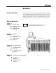
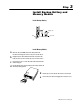
Configure I/O Chassis
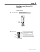
Set
the backplane switches.
a
Switch
Group
Assembly
See the installation manual for your particular processor
for specific switchsetting information.
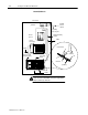
Install
keying bands.
See
the appropriate product data for the module
you are installing to determine the proper keying
positions for each module.
2
4
6
8
10
12
14
16
18
20
22
24
26
28
30
32
34
36
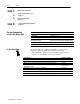
Keying
Bands
Backplane
Socket
10170-I
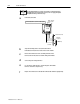
b
Insert two keying bands in the top backplane connectors of
the I/O chassis. For the processor, place one keying band
in the leftmost slot between pins 46 and 48 and 54 and 56.