Allen Bradley Mini PLC 2 Family Programmable Controllers product icon Quick Start for Experienced Users
Important User Information Because of the variety of uses for the products described in this publication, those responsible for the application and use of this control equipment must satisfy themselves that all necessary steps have been taken to assure that each application and use meets all performance and safety requirements, including any applicable laws, regulations, codes and standards.
Table of Contents Preface . . . . . . . . . . . . . . . . . . . . . . . . . . . . . . . . . . . . . . . P-1 Using this Quick Start . . . . . . . . . . . . . . . . . . . . . . . . . . . . . . . . . What You Need to Do . . . . . . . . . . . . . . . . . . . . . . . . . . . . . . . . . System Components used in this Quick Start . . . . . . . . . . . . . . . . If You Need Help ... . . . . . . . . . . . . . . . . . . . . . . . . . . . . . . . . . . P-1 P-1 P-2 P-2 Configure and Ground I/O Chassis . . . . . .
Preface Preface Using this Quick Start This quick start is designed to help you quickly install and connect a basic mini-PLC-2 family programmable controller system. Use this guide if you are knowledgeable about mini-PLC-2 family products but may not have used one or more of the products for a period of time. The information we provide is geared to “jog your memory.
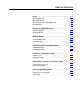
P–2 Preface step 5 a b step 6 Make power connections Connect power to processor (page 5 1) Connect power supply (page 5 1) Connect programming terminaal (page 6 1) System Components used in this Quick Start If You Need Help ... A B Publication 1772 10.
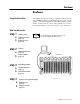
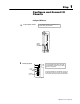
Step 1 Configure and Ground I/O Chassis Configure I/O Chassis a Set the backplane switches. See the installation manual for your particular processor for specific switch setting information. Switch Group Assembly b Install keying bands. Keying Bands Backplane Socket See the appropriate product data for the module you are installing to determine the proper keying positions for each module.
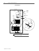
1–2 Configure and Ground I/O Chassis Ground I/O Chassis enclosure wall grounding electrode conductor ground bus to grounding electrode system equipment grounding conductor PLC 2/30 processor 8 AWG 1771 P7 power supply I/O chassis wall 14 AWG mini processor with built in power supply ground lug power supply module nut star washer ground lug 14 AWG ATTENTION: If you use this grounding configuration, do not make connections to EQUIP GND on the power supply terminal strips or ground loops could
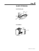
Step 2 Install I/O Modules Install Field Wiring Arms wiring arm horizontal bar C shaped bracket remove install Install I/O Modules locking bar I/O module card guides corresponding keyed slot Publication 1772 10.
2–2 Install I/O Modules For more information... a Specific wiring information for each type of I/O module is contained in the product data publication for that specific module. Therefore, refer to the appropriate product data publication when you follow these steps. Install each I/O module. Use the locking latch to secure the module in place.
Step 3 Install Backup Battery and Memory Module Install Backup Battery + battery cover - lithium battery cover screw Install Memory Module a Move the chassis POWER switch to the OFF position and turn off the incoming power source to the processor and chassis. b Unplug the power cable and lift the latch of the I/O chassis that holds your processor, then slide the processor out of the chassis. c Place the processor on a clean, flat surface with the bottom of the module facing you.
Step 4 Install Processor and Power Supply Install Processor locking bar Mini PLC 2/17 processor left most slot Install Power Supply If you have a processor with a power supply, and do not need additional current for your I/O modules, skip this step. If you need additional current, use an ac powered supply because we recommend that you use the same input voltage source for two paralleled power supplies.
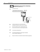
Step 5 Connect Power to the Processor or Power Supply Connect Power to Processor place tool here a Strip 3/32 inch insulation from the end of the wire. b Insert screwdriver into the square opening and press down with it. c Insert the wire into the round opening on the front of the plug and remove the screwdriver. insert wire here Connect Power Supply a b c Strip 3/8 inch insulation from the end of the wire. Loosen each terminal screw and place the appropriate wire under it.
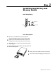
Step 6 Connect Programming Terminal a Turn the power switch on the front of the terminal to the OFF position and plug the ac power cord into the terminal. Mini PLC 2/02, 2/16, 2/17 Industrial Terminal (rear view) Channel A PLC 2 Family b Program Panel Interconnect Cable cat. no. 1772 TC 10 ft (3.05 cm) Interface If your processor has a power supply, plug the ac power cord into the ac power source.
6–2 Connect to a Personal Computer 62 pin D shell Connector Pin Male 10.2 cm (4 in.) 22 43 1 62 21 15 pin D shell Connector Pin Female 3.2 m (10.50 ft.) 10.2 cm (4 in.) 1784 CP2 cable 8 15 1 9 PLC 2 Processor Industrial Terminal 4 1 5 2 7 3 6 4 26 5 27 6 47 7 48 8 62 pin D shell Using 6200 Programming Software For more information... For specific information about using 6200 programming software, see the Mini PLC 2/02, 2/16, 2/17 Processor User Manual, publication 1772 6.
Appendix Specifications Specifications Specifications for Mini-PLC-2 processors follow. Mini PLC 2/02 Processor without a power supply (1772 LZ) Location Mini PLC 2/16 Processor without a power supply (1772 LX) Mini PLC 2/17 Processor without a power supply (1772 LW) 1771 I/O chassis left most slot Backplane Current 1.
A-2 Specifications Mini PLC 2/02 Processor with a power supply (1772 LZP) Mini PLC 2/16 Processor with a power supply (1772 LXP) Mini PLC 2/17 Processor with a power supply (1772 LWP) These processors have the same features as above and they also have a self contained power supply. Input Voltage 120/220 V ac (switch selectable) Input Voltage Range 97 to 132 V ac 194 to 264 V ac Nominal Input Power 96 VA Frequency Output Current to Backplane Keying (top connector) Publication 1772 10.
I–2 Allen Bradley, a Rockwell Automation Business, has been helping its customers improve productivity and quality for more than 90 years. We design, manufacture and support a broad range of automation products worldwide. They include logic processors, power and motion control devices, operator interfaces, sensors and a variety of software. Rockwell is one of the world's leading technology companies. Worldwide representation.