Allen Bradley Mini-PLC 2/15 Programmable Controller (Series B) Programming and Operations Manual
Table of Contents Introduction . . . . . . . . . . . . . . . . . . . . . . . . . . . . . . . . . . . . 1 1 Purpose . . . . . . . . . . . . . . . . . . . . . . . . . . . . . . . . . . . . . . . . . . To The Reader . . . . . . . . . . . . . . . . . . . . . . . . . . . . . . . . . . . . . . Vocabulary . . . . . . . . . . . . . . . . . . . . . . . . . . . . . . . . . . . . . . . . Manual Design . . . . . . . . . . . . . . . . . . . . . . . . . . . . . . . . . . . . . . Conventions . . . . . . . . . . . . . .
ii Table of Contents Section B - Relay Type Instructions . . . . . . . . . . . . . . . . . 5 4 Bit Examining Instructions . . . . . . . . . . . . . . . . . . . . . . . . . . . . . . Bit Controlling Instructions . . . . . . . . . . . . . . . . . . . . . . . . . . . . . . Branching Instructions . . . . . . . . . . . . . . . . . . . . . . . . . . . . . . . . 5 5 5 5 5 6 Section C - Timers and Counters . . . . . . . . . . . . . . . . . . . . 5 8 Timer/Counter Theory . . . . . . . . . . . . . . . . . . .
Table of Contents iii Section E - Block Transfer Instructions . . . . . . . . . . . . . . . 6 35 Introduction . . . . . . . . . . . . . . . . . . . . . . . . . . . . . . . . . . . . . . . . Basic Operation . . . . . . . . . . . . . . . . . . . . . . . . . . . . . . . . . . . . . Block Transfer Syntax . . . . . . . . . . . . . . . . . . . . . . . . . . . . . . . . Block Programming Instructions . . . . . . . . . . . . . . . . . . . . . . . . . Buffering Data . . . . . . . . . . . . . . . . . . . . . . .
iv Table of Contents Section C - Documenting A Sequencer Instruction . . 10 10 Objectives . . . . . . . . . . . . . . . . . . . . . . . . . . . . . . . . . . . . . . . . . Programming Limitations . . . . . . . . . . . . . . . . . . . . . . . . . . . . . . Bottle Filling Application . . . . . . . . . . . . . . . . . . . . . . . . . . . . . . . Documenting Your Program . . . . . . . . . . . . . . . . . . . . . . . . . . . . 10 10 10 11 10 12 10 12 Special Programming Techniques . . . . . . . . . . . . .
Chapter 1 Introduction NOTE: Read this chapter before you use the series B Mini-PLC-2/15 programmable controller (cat. no. 1772-LV). It will tell you how to use this manual properly and efficiently. Purpose The Mini-PLC-2/15 programmable controller has been revised to meet customer needs when programming. An additional EAF EPROM hardware feature has been added to meet your programming needs.
Chapter 1 Introduction Vocabulary To make this manual easier to read and understand, we avoid repeating product names wherever possible. We refer to the: Series B Mini-PLC-2/15 programmable controller as “the controller” or “the processor.” Execute Auxiliary Function as “EAF” Programmable Read Only Memory as “PROM” Erasable Programmable Read Only Memory as “EPROM” A glossary section located in the back of this manual clarifies technical terms.
Chapter 2 An Introduction to Programmable Controllers Objectives This chapter reviews general fundamentals common to our programmable controllers (PC’s). When you are finished, you will have read several important concepts that will help you understand this manual. You’ll be able to: Describe what a programmable controller does. List and describe the functions of the four major sections of a programmable controller. Describe how the four major sections of a programmable controller interact.
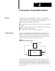
Chapter 2 An Introduction to Programmable Controllers Programmable Control Programmable controllers can perform many of the functions of traditional controls (Figure 2.2). Sensing devices and output devices are located at the machine and perform the same jobs. The field wiring between the machine and the control panel provides electrical paths from the sensing devices to the control panel, and from the control panel to the output devices. Figure 2.
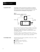
Chapter 2 An Introduction to Programmable Controllers Figure 2.3 The Four Major Sections of a Programmable Controller Power Supply Action Information Processor (Decision Making) Input Devices w Limit, Proximity, w w w w Pressure, Temperature Switches Push Buttons Logic BCD A/D Output Devices w w w w w w w Solenoids Motor Starters Indicators Alarms Logic BCD D/A 10719-I Power Supply The power supply provides a low level DC voltage source for the electronic circuitry of the programmable controller.
Chapter 2 An Introduction to Programmable Controllers Indication The input section of most modules also provides a visual indication of the state of each input terminal with indicators. The indicator is on when there is a voltage applied to its terminal. It is off when there is no voltage applied to its terminal. Since the indicator reveals the status of its terminal, it’s usually called an input status indicator. You should also notice another important characteristic of input indicators.
Chapter 2 An Introduction to Programmable Controllers In addition, the output section of modules with fuses has blown fuse indicators. Typically, each output circuit is fused in the output section. Groups of these fuses will have a blown fuse indicator associated with them. When one of the fuses in the group opens, the blown fuse indicator will be lit. Conditioning The output section conditions the programmable controller’s signals for the machine.
Chapter 2 An Introduction to Programmable Controllers Data Table The area of memory, where data is controlled and utilized, is called the data table. The data table is divided into several smaller sections according to the type of information to be remembered.
Chapter 2 An Introduction to Programmable Controllers Picture memory as a page that has been divided into many blocks. Each block represents one bit. you now know that each bit is either on or off. We could show the state of each bit by writing “on” or “off” into each block. However, there is an easier way. We can agree that the numeral one (1) means on and that the numeral zero (0) means off. We can easily and quickly show the status of each bit by writing one (1 or zero (0) into the appropriate block.
Chapter 2 An Introduction to Programmable Controllers For example, you may want the action to take place, “Whenever a certain limit switch closes.” So your condition could be, “If limit switch number two is closed,...” The action would be, “energize motor starter number one.” The entire statement would then read, “If limit switch number two is closed, then energize motor starter number one.
Chapter 2 An Introduction to Programmable Controllers Figure 2.4 A Simplified Example of a Machine with a Programmable Controller Controller Input Limit Switch Conveyor Output Conveyor Motor Unit 10144–I Since the limit switch is wired normally-closed, the conveyor motor will run until the arriving part opens the switch. At that time, the condition for energizing the motor will no longer be met. Therefore, the motor will be de-energized. When the condition is met, we say it is true.
Chapter 2 An Introduction to Programmable Controllers Figure 2.5 Scan Sequence Output Image Table Output Terminals Copy output image table status into output terminal circuits. I/O Scan Input Image Table Input Terminals Copy input terminal status into input image table ( ) Program Statement Program Scan Execute each program rung in sequence, writing into bits in the data table, including the output image table.
Chapter 2 An Introduction to Programmable Controllers Our program could been written this way If (Condition) Then (Action) Input bit 02 is off Turn output bit 02 on In our example, the CPU reads a 0 at input bit location 02 and knows that the condition has been met. The CPU then carries out the action instruction by writing a 1 into output bit location 02.
Chapter 2 An Introduction to Programmable Controllers Conclusion 2 12 Now that you have read the basic concepts to our programmable controllers, you can proceed to chapter 3. Chapter 3 explains the specific hardware features of the Mini-PLC-2/15 system.
Chapter 3 Mini PLC 2/15 System: An Overview Objectives This chapter focuses on the complete Mini-PLC-2/15 system. In this chapter you will read about: Major components General features Hardware features Optional features This chapter is a synopsis of our Mini-PLC-2/15 Assembly and Installation Manual, publication 1772-803.
Chapter 3 Mini-PLC-2/15 System: An Overview Figure 3.1 Mini PLC 2/15 Programmable Controller 18404 System Status Indicators These indicators are located on the front panel of the controller and power supply. They indicate error conditions and are labeled as: Processor Indicator: red State: On indicates that the processor is unable to scan the program and I/O. Off indicates no error.
Chapter 3 Mini-PLC-2/15 System: An Overview RUN Indicator: Green State: On indicates that the output devices respond to your program when the processor is in run or run program modes. Off indicates that the processor is in the program or test modes, either wit the keyswitch or using the remote mode select function. Response: On- The processor will begin operations. Off - When the processor is in the test mode, the program is executed while the outputs are disabled.
Chapter 3 Mini-PLC-2/15 System: An Overview TEST Function: You can test your program without enabling outputs. Response: All outputs are disabled. Program instructions are executed. RUN Function: Your program is continuously being scanned and executed. Response: Programmed instructions control the outputs. Program changes can not be made. RUN PROG (remote mode selection) Function: Lets you select the desired mode without having to turn the keyswitch.
Chapter 3 Mini-PLC-2/15 System: An Overview WARNING: Do not use the on-line programming feature of the Mini PLC-2/15 when the 1770-T3 industrial terminal is connected to the processor through a series A Communications Adapter Module (cat. no. 1771-KA). Unpredictable machine operation could result and cause damage to your equipment, and/or injury to your personnel.
Chapter 3 Mini-PLC-2/15 System: An Overview Terminal Strip Purpose: Provides wire connections for the power supply module. Hardware: Terminals L1 and L2 label the AC input connections. Battery Backup Purpose: Provides battery backup power for the processor’s memory. Power Supply: Two alkaline D size battery cells or one D size lithium battery cell.
Chapter 3 Mini-PLC-2/15 System: An Overview Off indicates that the outputs are de-energized when a fault is detected. WARNING: Switch number 1 should be set to OFF for most applications. This allows the processor to turn controlled devices OFF when a fault is detected. If this switch is set ON, machine operation can continue after fault detection and damage to equipment and/or injury to personnel could result. NOTE: Use the tip of a ballpoint pen to set the switch.
Chapter 3 Mini-PLC-2/15 System: An Overview EAF Instructions Purpose: Provides additional specific application instructions. Hardware: Optional EAF EPROMs are available through your local Allen-Bradley Distributor or Sales Representative. Function: Each EAF EPROM provides its own unique set of instructions for your application needs.
Chapter 3 Mini-PLC-2/15 System: An Overview NOTE: Refer to individual product data publications for your needs by contacting your local Allen-Bradley Distributor or Sales Representative. Industrial Terminal Purpose: To program your controller you need the Industrial Terminal System series B (cat. no. 1770-T3). Function: With your industrial terminal you can: Enter Monitor Edit Troubleshoot your program.
Chapter 3 Mini-PLC-2/15 System: An Overview Peripheral Equipment Purpose: Optional auxiliary hardware which serves as a support function to enable you to store or maintain your programs on a magnetic medium or in report form. Description: There are peripheral devices available to you. Examples are: Silent 700 Data Terminal Data Cartridge Recorder (cat. no. 1770-SB) HC High Speed Bidirectional Printer (cat. no.
Chapter 4 Memory Organization Objectives This chapter describes: Hardware and its relationship to your program Memory and its components In chapter 2 we described in general terms the processor’s memory section. Now we want to give you detailed concepts of the memory’s organization and its structure. Understanding these concepts will aid you in programming your processor.
Chapter 4 Memory Organization Figure 4.1 Word Address Equals Memory Bits Concept Example Hardware Terminology Hardware Terminology Input (1) or Output (0) Output: 0 Rack No. (Always 1) Rack No.: 1 Module Group No. (0-7) Module Group No.: 0 Terminal No. (00-07, 10-17) Terminal No.: 12 X X X/XX Word Address 0 1 0/12 Word Address Bit Address Data Table Terminology Hardware Bit Address Instruction Address vs.
Chapter 4 Memory Organization Conclusion: 128 I/O is the combined amount of usable bits utilized in the input image table and/or the output image table. Memory Memory is divided into three major sections: data table, user program, and a message storage area. These areas store input status, output status, your program instructions, and messages. Figure 4.2 shows these areas with their corresponding octal addresses.
Chapter 4 Memory Organization transfer of output data to output devices occur during I/O scan. If the status of the output instruction changes in the program then the on/off status of the output devices update during the I/O scan to reflect the change. To utilize the data table to its fullest capacity certain facts must be understood: The processor automatically reserves the first 128 words in the memory for the data table. You can increase the data table size in two word increments up to 256 words.
Chapter 4 Memory Organization Figure 4.3 Data Table Organization, Factory Configured Total Decimal Words 8 8 Bit Address Word Address Decimal Words Per Area Processor Work Area No. 1 000 00 007 010 17 00 017 020 17 00 026 027 030 17 077 100 17 00 107 110 17 00 117 120 17 00 Output Image Table 16 8 Bit/Word Storage 24 8 64 40 72 8 Reserved 1 2 Timer/Counter Accumulated Values (AC) 3 (or Bit/Word Storage) Processor Work Area No.
Chapter 4 Memory Organization Data Table Areas There are six areas (Figure 4.3) making up the data table. They are: Input image table Output image table Processor work areas (2) Timer/Counter accumulated values and internal storage Timer/Counter preset values and internal storage Chapter 2 discusses the input and output image tables. We will now discuss the remaining areas. Keep in mind that we are referring to a factory configured data table.
Chapter 4 Memory Organization The user program area begins at word address 200. Main Ladder Diagram Program Purpose: Your program is a group of ladder diagram and functional block instructions used to control an application. NOTE: The term ladder diagram is defined in chapter 5. Description: Refer to chapter 8 section A. Subroutine Area Purpose: Used to jump to a defined ladder diagram area. This will allow you to perform ladder diagram subroutines. Description: Refer to chapter 6 section B.
Chapter 4 Memory Organization any other functions if you want to achieve maximum flexibility within your program. When you enter the report generation message [M][S][,][0][RETURN] the terminal displays the prompt: MESSAGE CONTROL WORDS (Y DIGITS REQUIRED): where “Y” is the required 3 or 4 digits of a word address for the selected data table size. You must enter the beginning word address of the message control word file. The Industrial Terminal then calculates and displays the ending address.
Chapter 5 Fundamental Instruction Set Programming Logic: Objectives This chapter describes fundamental programming and editing techniques common to the controller. In this chapter you will read sections A through E concerning: Programming Logic Relay Type Instructions Timer and Counter Instructions Data Manipulation Instructions Arithmetic Instructions NOTE: Refer to the operations section of this manual for example instructions concerning chapters 5 and 6.
Chapter 5 Fundamental Instruction Set Perhaps an example might make this more clear: True True True C1 C2 C3 A Here, a series of conditions, (C1, C2, C3) must be true before an action is performed. C1 = Input switch 1. When the switch is on, this condition is true. This switch turns on a conveyer belt. C2 = Input sensor 1. When the sensor is off, this condition is true. This sensor detects if the temperature in the factory is below 40oC. C3 = Input sensor 2.
Chapter 5 Fundamental Instruction Set reset to a 0. (From this point on, set means turned to the on-condition or 1. Reset means turned to the off-condition or 0.) Address If the device : The a bit in memory is: on set off reset Recall that the controller scans the status of your inputs and controls your output devices. It does not go to the input or output terminals to see if outputs are on or off.
Chapter 5 Fundamental Instruction Set The second number denotes an I/O rack ad it always is a 1. The third number denotes a module group. This number will range from 0-7. The fourth and fifth numbers denote a terminal designation: 00-07 left slot of the module group 10-17 right slot of the module group Section B Relay Type Instructions Introduction You can use six relay type instructions to write a program (Figure 5.2).
Chapter 5 Fundamental Instruction Set Bit Examining Instructions Exami ne On Symbol: -| |Purpose: This instruction tells the controller to examine a bit at a specified memory location. Syntax: Programmed at the condition side of the rung. Function: Determines the instruction condition. The instruction condition becomes: True If the controller detects that a bit in memory is set. False If the controller detects that a bit in memory is reset.
Chapter 5 Fundamental Instruction Set Latch Symbol: -(L)Purpose: This instruction tells the controller to set a specified memory bit. It is used with the unlatch instruction. Syntax: Programmed at the output side of the rung. This is a retentive instruction. Retentive means that once the rung condition goes false, the latch bit remains set until reset by an unlatch instruction. Function: Controls a specific bit based on the rung condition.
Chapter 5 Fundamental Instruction Set The rung below uses parallel logic: False A C1 True C2 Here two conditions are parallel. As long as one of the conditions (C1 or C2) is true, a continuous path to the action exists. Therefore, the action is performed. True False C1 C2 True True C3 C4 A Figure 5.2 shows a program rung with branching, as it would appear by the 1770-T3 terminal display. You create a branch by using two different branch instructions.
Chapter 5 Fundamental Instruction Set The rung below achieves the same result, but avoids nested branching: 110 110 110 010 00 110 10 110 11 00 12 110 11 13 Section C Timers and Counters Introduction Timer and counter instructions are output instructions internal to the controller. They provide many of the capabilities available with timing relays and solid state timing/counting devices.
Chapter 5 Fundamental Instruction Set Two bits in the accumulated value word are status bits: Bit 15 is the timed bit. It is set either on or off wen the timer has timed out. The settings on or off depend on the type of timer instruction used. Bit 17 is the enable bit. It is set when rung conditions are true and is reset when rung conditions are false.
Chapter 5 Fundamental Instruction Set CAUTION: Allowances should be made for conditions which could be created by the use of the jump instruction. Jumped program rungs are not scanned by the processor so that input conditions are not examined and outputs that are controlled by these rungs remain in their last state. Timers and counters cease to function. Critical rungs should be reprogrammed outside the jumped section in the program zone.
Chapter 5 Fundamental Instruction Set Retentive Timer Instruction Symbol: -(RTO)Purpose: Similar to the TON instruction. The AC value is retained through false rung conditions. Syntax: Programmed as an output instruction. Function: When the rung condition becomes: True Timer begins counting time-base intervals. Bit 15 is set when AC=PR and the timer stops timing. Bit 17 is set. False Accumulated value is retained. Bit 15 - no action is taken. Bit 17 is reset.
Chapter 5 Fundamental Instruction Set The upper four bits in the accumulated value (AC) word are status bits: Bit 14 - Overflow/underflow bit. it is set to one when the AC value of the CTU instruction exceeds 999 or when the AC value of the CTD instruction falls below 000. Bit 15 - Count complete bit. it is set to on when the AC value >PR value. Bit 16 - Enable bit for CTD instruction. It is set on when the rung condition is true. Bit 17 - Enable bit for CTU instruction.
Chapter 5 Fundamental Instruction Set True Accumulated value increments by 1. Bit 14 is set on if the AC >999. Bit 15 is set on when AC >PR. Incrementing of the accumulated value can continue after the preset value is reached. Bit 17 is set and stays set until the rung goes false. False Accumulated value is retained. Bit 14 - no action is taken. Bit 15 is retained if it was set. Bit 17 is reset. The CTU retains its AC value when: You change the mode select keyswitch to the PROG position.
Chapter 5 Fundamental Instruction Set Counter Reset Instruction Symbol: -(CTR)Purpose: Resets the up counter or down counter instructions’ accumulated value and status bits to 0. Syntax: Programmed as an output instruction. The AC and PR values are displayed. Function: When the rung condition becomes: True Accumulated value of the specified counter is reset to 000. Status bits (14, 15, 16, 17) are reset. False No action is taken.
Chapter 5 Fundamental Instruction Set Figure 5.5 Get and Put 110 11 030 PUT 238 110 G 238 Put Symbol: -(PUT)Purpose: Receives 16 bits of data from the immediately preceding get instruction and stores the data at the specified data table word location. Used with a get instruction to form a data transfer rung. Syntax: Programmed in the output side of the ladder diagram rung (Figure 5.5). This instruction can have the same address as other instructions in the program.
Chapter 5 Fundamental Instruction Set Less Than Symbol: -|<|Purpose: Compares the data in your specified address with the data stored at another address in memory. It determines the rung condition. Syntax: Programmed after the get instruction in the condition side of the ladder diagram rung (Figure 5.7). Function: The rung condition becomes: True If the get value is less than the reference values stored in the less than instruction. False If the get value is not less than the less than value. Figure 5.
Chapter 5 Fundamental Instruction Set NOTE: Do not place compare instructions between the get byte and limit test instruction. The get byte and limit test instructions only work with octal values. Function: The rung condition becomes: True If the specified byte value is between the two reference values. False If the specified byte value is outside the reference values. Get Byte/Put Symbol: Figure 5.
Chapter 5 Fundamental Instruction Set Figure 5.
Chapter 5 Fundamental Instruction Set performs arithmetic and data manipulation operations only with 3-digit BCD values. Subtraction Symbol: -(-)Purpose: Reports the difference between two values stored in the get instruction words. The second get word value is subtracted from the first get word value. Syntax: programmed in the output position of the ladder diagram rung. Your difference is stored in the subtract instruction word address.
Chapter 5 Fundamental Instruction Set 000.000. This differs from the PLC-2/20 and PLC-2/30 controllers where 0 : 0 = 1.000.
Chapter 6 Advanced Instruction Set Objectives This chapter describes advanced programming techniques common to the controller.
Chapter 6 Advanced Instruction Set Figure 6.1 Scan Sequence Output Image Table Output Terminals Copy output image table status into output terminal circuits. I/O Scan Input Image Table Input Terminals Copy input terminal status into input image table ( ) Program Statement Program Scan Execute each program rung in sequence, writing into bits in the data table, including the output image table. 10150-I Next, the CPU scans the program. It does this statement by statement.
Chapter 6 Advanced Instruction Set NOTE: When your processor is in the test mode, all outputs are not active. When your processor is in the run mode, all outputs are active. Scan Time Scan time is the amount of time it takes the processor to monitor and update inputs and outputs, and to execute instructions in memory in accordance with your program. The scan is performed serially; first the I/o image table is updated, (other parts of the data table are not scanned), then the user program area is scanned.
Chapter 6 Advanced Instruction Set Figure 6.2 Rungs for Measuring Scan Time 031 Rung 1 031 CTU PR 999 AC 000 Rung 2 031 CTU PR 999 AC 000 Rung 3 032 RTO 0.1 PR 999 AC 000 15 ? 031 14 031 13 031 032 G Store 1 G 010 Rung 4 Store 3 : Rung 5 031 CTR PR 100 AC 000 Rung 6 032 RTR 0.1 PR 999 AC 000 14 031 Store 2 : 14 Here is an explanation of each rung: Rung 1: The count increments its accumulated value each time this rung is true.
Chapter 6 Advanced Instruction Set Rung 6: An input device is controlling the timer. Table 6.
Chapter 6 Advanced Instruction Set Instruction Name Symbol Instruction False Multiply (x) (x) 615 60 Divide (:) (:) 875 60 27 27 Add to any of the above when its address is 4008 or greater 6 6 Instruction True Master Control Reset (MCR) 23 20 Zone Control Last State[1] (ZCL) 83 28 Branch Start 18 13 Branch End 18 13 End, Temporary End T.
Chapter 6 Advanced Instruction Set Instruction Name File to file Move Symbol FILE 10 Instruction True Instruction False 470 200 [1]When a rung which contains a ZCL instruction is false, the execution time of each instruction between the start fence and end fence is 17 microseconds per word. If the scan time is over 130ms a watch dog timer (internal alarm system) will automatically timeout and the processor will shut down.
Chapter 6 Advanced Instruction Set Section B Program Control Instructions Introduction Certain applications may need programming techniques designed to override a group of non-retentive outputs or update I/O ahead of the usual I/O scan time. The program control instructions satisfies this need.
Chapter 6 Advanced Instruction Set Figure 6.3 MCR Programming MCR Start fence When MCR zone is false nonretentive outputs are deenergized MCR Unconditional end fence Function: If the start fence becomes: True Each rung condition controls their output instructions. False All non-retentive output instructions within the zone area de-energize by the MCR zone.
Chapter 6 Advanced Instruction Set Program the first ZCL instruction with input conditions to begin the zone (start fence). Program the second ZCL instruction unconditionally to end the zone (end fence). Do not nest ZCL zones with other ZCL or MCR zones. Each zone must be separate and complete. Figure 6.
Chapter 6 Advanced Instruction Set Function: Used where I/O modules interface with I/O devices that operate in a shorter time period than the processor scan. Immediate Input Update Symbol: -|I|Purpose: Updates one input image table word from one input module group in advance of the normal I/O scan sequence. Syntax: Programmed at the condition side of the logic rung just before inputs in the module group are examined in the program (Figure 6.5).
Chapter 6 Advanced Instruction Set Figure 6.5 Immediate Input Instruction I/O Scan Program Scan Immediate input instruction interrupts program scan 2 Examine bits in word 112 here in program Returns to Program Scan Word 112 16 bits from one module group written into input image table word Module Group (input) 10151 I Function: The instruction is always considered logic true and execution takes place whether or not other rung conditions allow logic continuity.
Chapter 6 Advanced Instruction Set NOTE: To avoid loss of production time use these instructions only when absolutely necessary. Figure 6.
Chapter 6 Advanced Instruction Set Section C Jump Instructions and Subroutine Programming Introduction You are capable of reducing scan time by using instructions that selectively jump over portions of a program. These instructions are: Jump Label Jump to subroutine Return This section describes how jump instructions and subroutine programming direct the path of the program scan through the main program and the subroutine area.
Chapter 6 Advanced Instruction Set Figure 6.
Chapter 6 Advanced Instruction Set A maximum of eight subroutines can be programmed in the subroutine area. Each subroutine begins with a label instruction and (when you want to exit to your main program) ends with a return instruction. We will discuss jump, label, and return instructions later in this section. Subroutine Area Instruction Symbol: SBR Purpose: Serves as an end of program statement for the main program (Figure 6.8). Figure 6.
Chapter 6 Advanced Instruction Set Syntax: Actual programming techniques are described in the operations section, chapter 9. Here we will state general programming facts: Uses one word of memory. Processor does not scan the instruction until you program a jump to subroutine instruction. Up to eight subroutines can be programmed if you do not program any jump instructions. Do not next subroutine programs by inserting a jump to subroutine instruction in the subroutine area. Figure 6.
Chapter 6 Advanced Instruction Set Jump Symbol: -(JMP)Purpose: Used with a label instruction to instruct the processor to jump forward in the main program to the label instruction with the same identification number. Executes in the main program. Syntax: Programmed as an output instruction. Do not program in an area where the jump instruction crosses the boundary between the main program and subroutine area, or vice-versa. Function: Execution takes place only on true conditions.
Chapter 6 Advanced Instruction Set WARNING: Do not place a label instruction in a ZCL or MCR zone. When jumping over a start fence, the processor will execute the program from the label to the end fence as if the start fence had been true, i.e. outputs controlled by the rungs. The start fence may have been false intending that all outputs within the zone be controlled by the output override instruction, i.e. off for MCR or last state for ZCL instructions.
Chapter 6 Advanced Instruction Set SECTION D Advance Data Manipulation This section describes ways to transfer file data to another designated area. In this section you will read about: Files Data monitor mode display Data transfer file instructions Sequencer instructions Chapter 10 demonstrates the programming techniques when using advanced data manipulation instructions. What is a File? A file is a group of consecutive data table words used to store information.
Chapter 6 Advanced Instruction Set Figure 6.10 Types of file Instructions Word To File Move 212 Counter Addr: 007 Position: 012 File Length: 113 Word Addr: 420433 File R: 212 DN 15 Externally Indexed FIle Instruction File To File Move Counter Adddr: Position: File Length: File A: File R: Rate Per Scan: 214 001 014 512- 527 562- 577 014 214 EN 17 214 DN 15 Internally Indexed File Instruction Externally Indexed Externally indexed means that you assign an accumulated value to the counter.
Chapter 6 Advanced Instruction Set Another characteristic of the internally indexed file instruction is that it has a done bit and an enable bit. The done bit is bit 15 and the enable bit is bit 17. These two bits are automatically entered from the counter address. The enable bit is set when the rung logic goes from a false to true transition; the done bit is set when the file instruction is completed. Modes of Operation There are three modes of operation based on the rate per scan.
Chapter 6 Advanced Instruction Set last group of words is operated upon. At the same time, the done bit is set and stays set for one scan. During the next scan the done bit is reset, and the counter is reset to position 001. Incremental Mode In the incremental mode, the rate per scan is equal to 0. This means that upon each false-to-true transition one word is operated upon per scan, then the counter increments to the next position. When the rung is true the enable bit (bit 17) is set.
Chapter 6 Advanced Instruction Set Data Monitor Mode Display Once you establish your file data, you’ll want to edit, load, or monitor your file data. To do these functions the processor has a data monitor mode. This mode lets you access your file in two ways: either by displaying binary values or hexadecimal values (Figure 6.11). The binary data monitor display lets you manipulate one word at a time by displaying each bit using binary digits.
Chapter 6 Advanced Instruction Set Figure 6.
Chapter 6 Advanced Instruction Set Data Transfer File Instructions There are three types of data transfer file instructions: File to file move File to word move Word to file move Refer to Figure 6.12 while you are reading about each file instruction. Figure 6.
Chapter 6 Advanced Instruction Set Here is an explanation of each value: Counter Address: Address of the instruction in the accumulated value area of data table. Position: Current word being operated upon (accumulated value of counter). File Length: Number of words in file (preset value of the counter). File A: Starting address of source file. File R: Starting address of destination file. Word Address: Address of source word or destination word outside of file.
Chapter 6 Advanced Instruction Set Word to File Move Symbol: FILE 11 Purpose: Duplicates and transfers the data of a word from the data table to a specified word within a file. Syntax: Programmed as an output instruction; requires 4 words of the user program area. Function: Your program must externally index the counter. When the rung goes: True Data from a designated word address in the data table is transferred to the selected position in the file. False No action is taken.
Chapter 6 Advanced Instruction Set WARNING: The counter address for the word-to-file move and file-to-word move instructions should be used only for the intended instruction and the corresponding instructions which manipulate the accumulated value. Do not inadvertently manipulate the preset or accumulated word. Changes to these values could result in unpredictable machine operation or a run time error. Damage to equipment and/or injury to personnel could occur.
Chapter 6 Advanced Instruction Set Figure 6.13 Sequencer Instructions Key Sequence SEQ 0 1779-T3 Display Sequencer Output 030 Counter Addr: Current Step: 001 Seq Length: 001 Words per Step: 1 File: 110 110 Mask: 010 010 Output Words 1: 010 2: 3: 4: Instruction Notes 030 EN 17 Output instruction. 030 DN 15 Same data transferred each scan that the rung is true. Increments, then transfers data. Counter is indexed by the instruction. Unused output bits can be masked.
Chapter 6 Advanced Instruction Set Here is an explanation of each value: Counter Address: Address of the instruction in accumulated value area of data table. Current Step: Position in sequencer table (accumulated value of counter). Seq Length: Number of steps (preset value of the counter). Words per Step: Width of sequencer table. File: Starting address of sequencer table. Mask: Starting address of mask file. Output Words: Words controlled by the instruction.
Chapter 6 Advanced Instruction Set If the rung condition becomes: True Action is taken. False No action is taken. WARNING: The counter address of the sequencer input instruction should be used only for the intended instruction and the corresponding instructions which manipulate the accumulated value. Do not inadvertently manipulate the preset or accumulated word. Changes to these values could result in unpredictable machine operation or a run-time error. Damage to equipment and/.
Chapter 6 Advanced Instruction Set Outputs remain in their last state unless changed by instructions elsewhere in your program. WARNING: The counter address of the sequencer output instruction should be reserved for that instruction. Do not manipulate the counter preset or accumulated word. Changes to these values could result in unpredictable machine operation or a run-time error. Damage to equipment and/or injury to personnel could occur.
Chapter 6 Advanced Instruction Set WARNING: The counter address of the sequencer load instruction should be reserved for that instruction. Do not manipulate the counter accumulated or preset word. Changes to these values could result in unpredictable machine operation or a run-time error. Damage to equipment and/or injury to personnel could occur.
Chapter 6 Advanced Instruction Set SECTION E Block Transfer Instructions Introduction Block transfer refers to a set of instructions and a programming technique used to transfer many words of data in one I/O scan. You can transfer data either from intelligent 1771 I/O modules to the processor’s data table or from the processor’s data table to the intelligent 1771 I/O modules.
Chapter 6 Advanced Instruction Set Figure 6.
Chapter 6 Advanced Instruction Set Table 6.
Chapter 6 Advanced Instruction Set Figure 6.15 Block Transfer Format Block Xfer Read 030 Data Addr: 100 Module Addr: 01 Block Length: 110 110 File: Block Xfer Write Data Addr: Module Addr: Block Length: 110File: 030 100 01 110 010 EN 07 110 DN 07 010 EN 06 110 DN 06 NOTE: Numbers shown are default values. Numbers in shaded areas must be replaced by user-entered values. The number of default address digits initially displayed (3 or 4) will depend on the size of the data table.
Chapter 6 Advanced Instruction Set programmed by assigning the get and put instructions to the address immediately following the last block transfer data address. The value of the get instruction is reset to 000 when programmed. Defining the Block Transfer Data Address Area When the block transfer instructions are used, the first word and consecutive words of the timer/counter accumulated area of the data table must be reserved for block transfer data addresses.
Chapter 6 Advanced Instruction Set Done and Enable Bits The read and write bits are the enable bits for block transfer modules. Either one (or both for a bidirectional transfer) is set in the program scan when the rung containing the block transfer instruction is true. The done bit is set in the I/O scan that the words are transferred, provided that the transfer was initiated and successfully completed. The done bit remains set for only one additional program scan.
Chapter 6 Advanced Instruction Set Function: Acts upon false-to-true transitions. When the rung goes: True Data is transferred. False No action is taken. Block Transfer Write Symbol: BLOCK X-FER 0 Purpose: Writing information from the processor’s output image table to the 1771 I/O module in one I/O scan. Syntax: Programmed as an output instruction. This instruction requires two words of your program. Function: Acts upon false-to-true transitions when the rung goes: True Data is transferred.
Chapter 6 Advanced Instruction Set respective user’s manual for the block transfer module to determine the correct usage of the diagnostic and/or data valid bit(s). One technique of buffering data is to store the transferred data in a temporary buffer file. If the data in the buffer is valid, it is immediately transferred to another file in the data table where it can be used. If invalid, it is not transferred but written over in the next transfer. Another technique uses only one file.
Chapter 6 Advanced Instruction Set Figure 6.16 Buffering Data R 1 1 0 Block Length Code 4 0 014 030 Data in the buffer file 050-052 will be moved to 150-152 when: 050 A. Done Bit 114/07 is set (Valid transfer) Block Transfer Data (Buffer) 052 R 1 0 0 5 B.
Chapter 7 Operations Overview To the Reader This section is the operations section. it will get you started in programming by giving you step by step directions for relay type instructions and editing functions. This section is not designed to give detailed instructions for all of our commands located within the Industrial Terminal (cat. no. 1770-T3). We designed a Quick Reference section to let you familiarize yourself with the commands.
Chapter 7 Operations Overview Some keys have two symbols occupying one key (Figure 7.1). To display the top section of each key use your shift key before the desired symbol. For example: A 7 Press To display 7 [Shift] To display A Figure 7.1 PLC 2 Family Keytop Overlay MODE SELECT DATA INIT EXPAND ADDR RECORD RUNG SBR (RET) LBL EAF T.
Chapter 7 Operations Overview 5. Connect the AC power cord of the industrial terminal to the incoming AC power source. 6. Connect one end of the PLC-2 Program Panel Interconnect Cable (cat. no. 1772-TC) to CHANNEL A at the rear of the industrial terminal. 7. Connect the other end of the cable to the socket labeled INTERFACE at the front of the controller. 8. Place the PLC-2 Family Keytop Overlay (cat. no. 1770-KCB) onto the keyboard. 9.
Chapter 8 Programming Fundamental Instructions Objectives This chapter shows how to program the fundamental instructions. In this chapter you will read how to: Enter rungs using relay type instructions. Insert an instruction into an existing rung. Remove an instruction from an existing rung. Edit an existing rung. System Start Up Power up your industrial terminal by turning the ON/OFF switch clockwise. The switch is located to the right of the screen (Figure 8.1). Figure 8.
Chapter 8 Programming Fundamental Instructions Figure 8.2 Press the Keys 11 to begin Programming Diagnostics Passed Mode Selection Keyboard Module 1770 FDC Series B/E Mode: Insert Keytop Overlay: 10 = PLC 11 = PLC-2 1770-KBA 1770-KCB 12 = Alphanumeric 1770-KAA For Use with the following processors PLC Mini PLC 2, PLC 2 Mini PLC 2/15 PLC-2.
Chapter 8 Programming Fundamental Instructions Relay Type Instructions Examine On, Examine Off, Energize We will begin by entering this rung: 114 112 013 13 10 01 NOTE: The cursor is located where you see the intensified part of the rung.
Chapter 8 Programming Fundamental Instructions Branch Instructions We will enter this rung: 112 112 013 10 11 112 01 12 DISPLAY KEY 010 11210 • 00 112 10 112 10 112 11211 8 4 + 010 10 00 112 112 10 11
Chapter 8 Programming Fundamental Instructions DISPLAY KEY • 11212 112 112 10 11 112 112 10 11 010 112 10 00 112 11 112 12 • 112 112 10 11 112 12 01310 + 112 112 010 10 11 112 00 12 112 112 013 10 11 112 01 12 8 5
Chapter 8 Programming Fundamental Instructions Bit Controlling Instructions Energize, Latch, Unlatch This is your final result: 112 013 12 13 013 L OFF14 013 U OFF14 112 13 112 14 DISPLAY KEY 010 11212 00 112 12 01313 112 010 12 00 013 112 12 010 13 00 11213 L 112 13 112 13 112 13 010 00 8 6 010 L OFF00 013 L OFF14
Chapter 8 Programming Fundamental Instructions DISPLAY KEY 11214 112 14 112 U 14 01314 112 14 010 U OFF00 013 U OFF14 SEARCH A blank Screen 112 013 12 13 112 13 112 14 013 L OFF14 013 U OFF14 Now practice inserting the following rungs: 112 112 013 02 04 113 01 112 01 112 112 013 02 04 12 02 112 03 112 13 112 013 03 12 112 10 8 7
Chapter 8 Programming Fundamental Instructions Section B Editing Your Instructions Objectives This section demonstrates: How to enter instructions. How to remove instructions from a rung. How to add rungs to your program. How to remove rungs from your program.
Chapter 8 Programming Fundamental Instructions When you are finished it should look like this: 112 112 013 10 11 112 01 12 DISPLAY KEY (cursor left) INSERT • 112 013 10 01 INSERT appears at the lower left hand corner of the screen. 112 013 + ? 10 INSERT 11211 INSERT • 01 INSERT appears at the lower left hand corner of the screen. 112 010 10 00 112 112 10 11 013 01 ? 013 01 INSERT appears at the lower right hand corner of the screen.
Chapter 8 Programming Fundamental Instructions DISPLAY KEY 11211 112 112 10 11 010 112 10 ? 013 01 ? 00 112 ? 11 112 013 01 ? 12 INSERT • • INSERT appears at the lower right hand corner of the screen. 112 112 013 10 11 112 01 + 12 Now we will remove this ranched instruction: 112 11 112 12 112 10 112 013 11 112 01 12 112 112 013 10 11 112 01 + 12 REMOVE 8 10 REMOVE appears at the lower left hand corner of the screen.
Chapter 8 Programming Fundamental Instructions DISPLAY KEY • REMOVE REMOVE • • REMOVE 112 112 112 013 10 11 12 01 REMOVE appears at the lower left hand corner of the screen. 112 112 013 10 11 01 REMOVE appears at the lower left hand corner of the screen. 112 112 10 11 01 112 112 013 10 11 01 ? REMOVE appears at the lower left hand corner of the screen. 112 10 112 ? ? 10 REMOVE • 013 013 01 013 01 REMOVE appears at the lower left hand corner of the screen.
Chapter 8 Programming Fundamental Instructions DISPLAY KEY 01302 112 013 11 02 112 013 11 You are done inserting the first new rung. Let's insert the second rung: 02 010 11212 00 112 12 01303 112 010 12 00 112 013 11 03 This completes the insertion of the second rung. (cursor up) 112 013 11 02 112 013 12 03 112 013 10 01 112 013 11 02 112 013 12 03 This is the complete program.
Chapter 8 Programming Fundamental Instructions To remove the middle rung from the existing program. 112 013 10 01 112 013 11 02 112 013 12 03 DISPLAY KEY (cursor down) REMOVE RUNG 112 013 10 01 112 013 11 02 112 013 12 03 112 013 11 02 112 013 12 03 REMOVE appears at the lower left hand corner of the screen.
Chapter 8 Programming Fundamental Instructions Practic by completing the exercie below: Start by entering: Then enter: 112 013 02 01 112 112 013 02 04 112 01 05 Now remove: 112 05 and 112 04 Add the following two rungs to your program: 112 013 03 02 112 013 04 03 112 013 03 02 112 013 Finally remove this rung: Your final result should be: 8 14 02 01 112 013 04 03
Chapter 9 Programming Applications Objectives This chapter illustrates generic programming applications which demonstrate a suggested use for the following instructions: Timer/counters Arithmetic Data manipulation Program control Do not program these examples using on-line production equipment. These examples are used only for demonstration purposes. Application One Refer to Figure 9.1. This application illustrates the conversion of temperature from Celsius to Fahrenheit.
Chapter 9 Programming Applications Figure 9.1 Converting Temperature Values 200 G 200 G 100 100 203 G 204 G 900 005 205 G 207 G 180 032 210 G 211 < 212 190 033 Rung 1 202 X 000 203 X 900 Rung 2 205 : 180 . 206 : 000 Rung 3 210 + 212 Rung 4 033 TON 1.
Chapter 9 Programming Applications Rung 6: Counter 034 counts the number of times the value falls below 1900F. Therefore, when rung 4 is true the counter increments. Rung 7: When the temperature equals 2120F, latch 11014 enables an alarm or an annunciator device. Rung 8: To unlatch the alarm, an operator would press a pushbutton connected to address 01116 that would shut the alarm off. Application Two Refer to Figure 9.2.
Chapter 9 Programming Applications Rungs 3 thru 5: Convert Celsius temperature to Fahrenheit temperature exactly as in application one. Rung 6: The return instruction signals the processor to return to the main program area. CAUTION: Allowances should be made for conditions which could be created by the use of the jump instruction. Jumped program rungs are not scanned by the processor so that input conditions are not examined and outputs that are controlled by these rungs remain in their last state.
Chapter 9 Programming Applications Figure 9.3 Program Control Instructions 110 Rung 1 MCR 17 110 16 Rung 2 Rung 3 011 15 MCR Master Control Reset 110 Rung 1 17 110 Rung 2 ZCL 011 15 16 Rung 3 ZCL Using the MCR instruction, rung logic would denote: If address 11017 is true, then address 01115 will work normally. If address 11017 is false, then address 01115 will be reset. Using the ZCL instruction, rung logic would denote: If address 1117 is true, then address 01115 will work normally.
Chapter 10 Block Format Instructions Objectives In this chapter you will read sections A thru C concerning: How to expand the data table. How to enter a file instruction. How to load data into the hexadecimal data monitor display. How to edit your file data. How to document a sequencer input and output instruction. How to enter a sequencer input and output instruction. How to load data into the binary data monitor display.
Chapter 10 Block Format Instructions Before you begin: Turn the keyswitch to the program position (PROG). As we stated in chapter 4, you must expand the data table to provide additional space for files. To do this: DISPLAY KEY SEARCH No display is on the screen DATA TABLE CONFIGURATION 50 NUMBER OF 128-WORD D.T. BLOCKS NUMBER OF INPUT/OUTPUT RACKS NUMBER OF T/C (if applicable) DATA TABLE SIZE 02 2 104 256 The above chart shows a factory configured data table.
Chapter 10 Block Format Instructions KEY DISPLAY 010 11205 00 112 05 FILE Screen does not change.
Chapter 10 Block Format Instructions DISPLAY KEY Now the cursor is on the first digit of the file length. 007 112 05 File to File Move Counter Addr: Position: File Length: File A: File R: Rate Per Scan: 0200 001 007 0000-0000 0000-0000 000 File to File Move Counter Addr: Position: File Length: File A: File R: Rate Per Scan: 200 001 007 0400 0406 0000-0000 000 200 EN 17 200 DN 15 The cursor moved to the first digit of file A.
Chapter 10 Block Format Instructions You can now proceed to add data to your file by using the data monitor display. Do not press [CLEAR MEMORY]. DATA MONITOR DISPLAY 112 File to File Move Counter Addr: Position: File Length: File A: File R: Rate Per Scan: 05 0200 001 007 0400 0406 0500 0507 007 200 EN 17 200 DN 15 Position your cursor on the words FILE TO FILE MOVE. Use the arrow keys to move your cursor. For this example we will use the hexadecimal data monitor display.
Chapter 10 Block Format Instructions We will now enter data in position 001. DISPLAY KEY 1257 HEXADECIMAL DATA MONITOR FILE TO FILE MOVE COUNTER ADDR: 200 FILE A: 400-406 POSITION: 001 POSITION 001 002 003 004 005 006 007 FILE A DATA 0000 0000 0000 0000 0000 0000 0000 FILE LENGTH: 007 FILE R: 500-506 FILE R DATA 0000 0000 0000 0000 0000 0000 0000 DATA : 1257 NOTE: If you made a mistake you can correct it by moving the cursor to the incorrect number and then pressing the correct number key.
Chapter 10 Block Format Instructions DISPLAY KEY 0721 HEXADECIMAL DATA MONITOR FILE TO FILE MOVE COUNTER ADDR: 200 FILE A: 400-406 POSITION: 001 POSITION 001 002 003 004 005 006 007 FILE A DATA 1257 0000 0000 0000 0000 0000 0000 FILE LENGTH: 007 FILE R: 500-506 FILE R DATA 0000 0000 0000 0000 0000 0000 0000 DATA : 0721 The cursor is on the value 1.
Chapter 10 Block Format Instructions Proceed by loading each position of file A with following data: POSITION 003 0879 POSITION 004 0162 POSITION 005 1982 POSITION 006 9715 POSITION 007 5761 Now file A is loaded. DISPLAY KEY Press a corresponding input address 11205: using an Input/Output Simulator (cat. no. 1790-DP). Notice that the data in file A transferred to file R.
Chapter 10 Block Format Instructions Let's Begin Your screen should look like this: DISPLAY KEY DISPLAY The screen does not change 1 HEXADECIMAL DATA MONITOR FILE TO FILE MOVE COUNTER ADDR: 200 FILE A: 400-406 POSITION: 001 POSITION 001 002 003 004 005 006 007 FILE A DATA 1257 0721 0879 0162 1982 9715 5761 FILE LENGTH: 007 FILE R: 500-506 FILE R DATA 1257 0721 0879 0162 1982 9715 5761 DATA : 0000 Notice that you now see a command buffer at the bottom of the screen. it is labeled DATA: 1257.
Chapter 10 Block Format Instructions DISPLAY KEY INSERT HEXADECIMAL DATA MONITOR FILE TO FILE MOVE COUNTER ADDR: 200 FILE A: 400-406 POSITION: 001 POSITION 001 002 003 004 005 006 007 FILE A DATA 1257 0721 0879 0281 1982 9715 5761 DATA : 0281 FILE LENGTH: 007 FILE R: 500-506 FILE R DATA 1257 0721 0879 0162 1982 9715 5761 Notice that FILE R’s POSITION has not changed. Not practice by changing the data in POSITION 006 of file A to 7777. Start by moving your cursor to POSITION 006.
Chapter 10 Block Format Instructions Mask A special programming technique called a “mask” is used with the sequencer instructions. By masking your bits you will be able to conserve bits and use them for storage. Definition A mask is a means of selectively screening out data. The purpose of the mask is to allow unused bits in the specific instruction to be used independently. For example, the number of output bits required for sequential operation can be any integer up to 64.
Chapter 10 Block Format Instructions When programming a sequencer input with a sequencer output instruction, the counter address for both instructions may be the same. Bottle Filling Application This application starts when a bottle is placed on a conveyor, it ends when the bottle is filled and ready for the next sequence of operations. This application is totally automated. Again, we emphasize that this application is only for demonstration purposes.
Chapter 10 Block Format Instructions Task 2: List Your Devices Input Devices The input devices and their abbreviations are: Input Device Abbreviation Comment Photocell PC Bottle in Place Fill tube extended LS1 Limit Switch Fill tube retracted LS2 Limit Switch Automated Auto Type of Operation Timer Timer 3 Seconds Output Devices The output devices and their abbreviations are: Output Device Abbreviation Conveyor motor CM Conveyor motion forward CMF Fill tube motor FTM Fill tube forw
Chapter 10 Block Format Instructions Task 3: Completing Your Worksheets Figure 10.1 and Figure 10.2 illustrate completed sequencer worksheets. Notice that the first step of the sequencer output is the last step of your operation. Table 10.A describes each step. To aid you in understanding this documentation concept, read Table 10.A while looking at each figure. Table 10.A NOTE: Read this table from left to right while looking at Figure 10.1 and Figure 10.2.
Chapter 10 Block Format Instructions Figure 10.
Chapter 10 Block Format Instructions Figure 10.
Chapter 10 Block Format Instructions Task 4: Processor Instruction Program Figure 10.3 is an example of a program rung which represents your worksheets. Figure 10.
Chapter 10 Block Format Instructions DISPLAY KEY SEQ The screen does not change 112 1 13 SEQUENCER INPUT COUNTER ADDR: CURRENT STEP: SEQ LENGTH: WORDS PER STEP FILE: MASK 0030 000 001 1 0110-0110 0010-0010 INPUT WORDS: 1: 0010 2: 3: 4: Notice that the words SEQUENCER INPUT are flashing, the cursor is on the first digit of counter address, and the default values are shown. Insert the following values. your cursor will move automatically throughout the block instruction.
Chapter 10 Block Format Instructions We will continue to insert data for the sequencer output instruction.
Chapter 10 Block Format Instructions Let’s continue and load your data into the binary data monitor mode for each sequencer instruction. You will get your data from your worksheets (Figure 10.1 and Figure 10.2). A filled in block means that a 2 will be inserted in a corresponding bit position. Start by positioning your cursor on the words SEQUENCER INPUT. Use the cursor control keys to move the cursor.
Chapter 10 Block Format Instructions DISPLAY KEY 0000001000000000 BINARY DATA MONITOR SEQUENCER INPUT STEP: 001 COUNTER ADDR: 200 SEQUENCER LENGTH: 006 FILE: 900-913 INPUT ADDR: 110 DATA: 00000000 00000000 00000000 201 00000000 MASK ADDR: 070 DATA: 00000000 00000000 00000000 071 00000000 STEP 001 002 003 004 005 006 PROGRAM MODE INSERT COUNTER ADDR: 200 WORD 1 WORD 2 00000000 00000000 00000000 00000000 00000000 00000000 00000000 00000000 00000000 00000000 00000000 00000000 00000000 00000000
Chapter 10 Block Format Instructions KEY DISPLAY BINARY DATA MONITOR SEQUENCER INPUT STEP: 001 COUNTER ADDR: 200 SEQUENCER LENGTH: 006 FILE: 400-413 INPUT ADDR: 110 DATA: 00000000 00000000 00000000 201 00000000 MASK ADDR: 070 DATA: 00000000 00000000 00000000 071 00000000 STEP 001 002 003 004 005 006 WORD 1 00000010 00000000 00000000 00000000 00000000 00000000 00000000 00000000 00000000 00000000 00000000 00000000 00000000 00000000 00000000 00000000 00000000 00000000 DATA: 00000000 PROGRAM M
Chapter 10 Block Format Instructions KEY DISPLAY INSERT BINARY DATA MONITOR SEQUENCER INPUT STEP: 001 COUNTER ADDR: 200 SEQUENCER LENGTH: 006 FILE: 400-413 INPUT ADDR: 110 DATA: 00000000 00000000 00000000 201 00000000 MASK ADDR: 211 DATA: 00000000 00000000 00000000 212 00000000 STEP 001 002 003 004 005 006 WORD 1 00000000 00000010 00000001 00000010 00000000 00000000 00000000 00000000 00000000 00000000 00000000 00000000 WORD 2 00000000 00000000 00000000 00000000 00000000 00000000 00000000 00
Chapter 10 Block Format Instructions Data is transferred to step 002. Continue adding your data: 003: 00000010 00010000 004: 00000010 00010001 005: 00000010 01000001 006: 00000010 00000000 To add data to WORD 2 press [SHIFT] [ ]. Data for word 2 step 004 is: 00100000 00000000 Press [CANCEL COMMAND] to display your rung. Position your cursor on the words SEQUENCER OUTPUT.
Chapter 10 Block Format Instructions A completed display for the sequencer output instruction looks like: BINARY DATA MONITOR SEQUENCER INPUT STEP: 001 COUNTER ADDR: 200 SEQUENCER LENGTH: 006 FILE: 600-613 INPUT ADDR: 012 DATA: 00000000 00000000 00000000 013 00000000 MASK ADDR: 075 DATA: 00000000 00000000 00000000 076 00000000 STEP 001 002 003 004 005 006 PROGRAM MODE WORD 1 00000000 00000010 00000001 00000010 00000001 00000010 00000001 00000010 00000001 00000010 00000000 00000010 WORD 2 00000
Chapter 11 Special Programming Techniques Objectives This chapter describes special programming techniques.
Chapter 11 Special Programming Techniques NOTE: If a particular function or instruction directory or an item in a directory is not available with the Mini-PLC-2/16 processor, the industrial terminal will display a “FUNCTION NOT AVAILABLE WITH THIS PROCESSOR” message if the key sequence is pressed. On Line Data Change You can change (while the processor is in the run/program mode) the lower 12 bits of a word or word instruction.
Chapter 11 Special Programming Techniques On line Programming Procedure The changes to your program that you can make in the on-line programming mode include the following: Insert an instruction Remove an instruction Insert a rung Remove a rung Change an instruction or instruction address The on-line programming mode is accessible from the industrial terminal by pressing the key sequence [SEARCH][5][2]. The processor keyswitch must be in the RUN/PROG position.
Chapter 11 Special Programming Techniques The data stored at the instruction address is divided into two sections: status bits (bits 14-17) and BCD values (bits 00-13). During program execution, these bits are constantly changing to reflect current states and values of program instructions. Therefore, when programming on-line, a decision must be made whether to use the current data or enter new data. Use the [DATA INIT] key when adding an instruction containing new data.
Chapter 11 Special Programming Techniques If found, the rung containing the first occurrence of the address and/or instruction will be displayed as well as the rungs after it. if the [SEARCH] key is pressed again, the next occurrence of the address and/or instruction will be displayed. When it cannot be located or all addresses and/or instructions have been found, a “NOT FOUND” message will be displayed.
Chapter 11 Special Programming Techniques DISPLAY KEY BLOCK X-FER No display.. 1 BLOCK XFER READ DATA ADDR: 303 MODULE ADDR: 100 BLOCK LENGTH: 01 FILE: 0110-0110 NOTE: If you cannot remember the number identifier for these instructions then press [BLOCK X-FER][HELP] File in the instruction’s parameters.
Chapter 11 Special Programming Techniques Here is a explanation to help you understand the sample rung: 1. During the program scan when input switch 11302 is true, the read enable bit 01217 is set to 1. 2. In the next scan of the output image table, the data in 01217 is sent to the module. 3. The I/O module responds (ready for transfer). 4. The processor interrupts the output image table scan and begins to search the timer/counter’s accumulated area of the data table. 5.
Chapter 11 Special Programming Techniques Refer to the user’s manual for additional information on the block transfer module of interest or consult our Publication Index (publication SD499). The programming example shown in Figure 11.2 shows how multiple reads of different block lengths from one module can be programmed. when any one of the input switches is closed, the rung is enabled and the block length is established.
Chapter 11 Special Programming Techniques WARNING: When programming multiple writes (or reads) to the same module, programming errors could prevent the desired transfer from taking place or limit the number of words transferred. Invalid data could be sent to an analog output device (or could be operated upon in subsequent scans) resulting in unpredictable machine operation. Damage to equipment and/or injury to personnel could occur.
Chapter 11 Special Programming Techniques Data Address and Module Address - The module address is stored in BCD in the data address of the read and write instructions. In this example, the module address is 130: rack 1, module group 3, slot 0. Two data addresses must be used. In this example they are 040 and 041. Both contain the module address. For bidirectional operation, each data address word also contains an enable bit; bit 16 for a read operation (in 040).
Chapter 11 Special Programming Techniques Unequal Block Lengths - Consult the user’s manual for the block transfer module of interest for programming guidelines when setting the block lengths to unequal values. Our Publication Index (publication SD499) lists the specific manuals. WARNING: When the block lengths of the bidirectional block transfer instructions are set to unequal values, the rung containing the alternate instruction must not be enabled until the done bit of the first transfer is set.
Chapter 11 Special Programming Techniques Figure 11.4 Leading Edge One Shot 112 011 253 04 14 00 253 00 112 04 One-shot storage bit 011 L 14 011 U 14 253 One-shot output 00 When bit 11204 makes a transition, the one-shot bit (bit 25300) is set on for one scan. The length of time bit 11204 remains on does not affect the one-shot bit due to the next two rungs. Bit 01114 will be latched on when bit 11204 is on or bit 01114 will be unlatched when 11204 is off.
Chapter 11 Special Programming Techniques When bit 11204 goes true, bit 01114 is latched on. As soon as bit 11204 makes a true-to-false transition, the one-shot bit (bit 25300) is set on and bit 01114 is unlatched. Bit 15300 will remain on for only one scan. The input bit 11204 must make a false-to-true transition then a true-to-false transition to set the one-shot bit for another scan. Manual Restart You can control start-up manually when using the EPROM back-up memory.
Chapter 11 Special Programming Techniques The values in the data table at start-up will depend on whether or not the memory was retained by back-up battery. If a battery was used, the data table will contain the values which existed when power was removed. If no battery was used, the values programmed into EPROM will be transferred into the data table at power-up.
Chapter 11 Special Programming Techniques Figure 11.8 24 Hour Clock 030 Rung 1 030 TON Seconds 1.0 PR 060 AC 000 Rung 2 031 CTU Minutes PR 060 AC 000 Rung 3 032 CTU PR 024 Hours AC 000 Rung 4 031 CTR PR 060 Resets AC 000 the clock Rung 5 032 CTR PR 024 AC 000 15 030 15 031 15 031 15 032 15 A synopsis of the operation’s cycle is: Rung 1: When the conditions are true the timer will start. Rung 2: When AC=PR (accumulated value equals preset value) of the timer, counter 031 increments.
Chapter 12 Run Time Errors Objectives In this chapter you will read: What are run time errors? Diagnosing a run time error. Causes of run time errors. What are Run Time Errors? Run time errors are errors that occur while the processor executes your program, and are only apparent during this time. These errors result from improper programming techniques. For example, it is possible to program a series of instructions in which the processor cannot properly perform the operation.
Chapter 12 Run Time Errors Table 12.A Possible Causes of Run Time Errors Instruction Jump Cause Jumping from the main program into the subroutine area or vice versa. Jumping backwards. Omitting the label instruction corresponding to the jump instruction. Jumping over a temporary end instruction. Label Multiple placement of the same label identification number. Removing a label instruction but leaving its refer ence, the jump or jump to subroutine instructions.
Chapter 13 Troubleshooting Aids Objectives Troubleshooting aids are useful during start-up of your operations and when troubleshooting your Mini-PLC-2/15 programmable controller system. They are: Bit manipulation function Bit monitor function force on and force off functions Temporary end instruction ERR message display We will discuss each troubleshooting aid. Bit Manipulation Function Bit manipulation allows the status of the displayed bits to be selectively changed or forced.
Chapter 13 Troubleshooting Aids Bit Monitor Function Bit monitor lets you display the status of all 16 bits of any data table word. It can function when the processor is in any mode. By pressing [SEARCH][5][3] (key sequence of word address), the status of all 16 bits of the desired word will be displayed. While the cursor is in the word address filed, use the [→] and [←] keys to change address digits.
Chapter 13 Troubleshooting Aids You can remove all force on or all force off functions at once in ladder diagram display by pressing either of the following key sequences: [FORCE ON] [CLEAR MEMORY] [FORCE OFF] [CLEAR MEMORY] The on or off status of a forced bit will appear beneath the bit instruction in the rung. In all processor modes, a “FORCED I/O” message is displayed near the bottom of the screen when bits are forced on or off.
Chapter 13 Troubleshooting Aids Temporary End Instruction You can use the temporary end instruction to test or debug a program up to the point where it is inserted. It acts as a program boundary because instructions below it in user program are not scanned or operated upon. Instead, the processor immediately scans the I/O image table followed by user program from the first instruction to the temporary end instruction.
Chapter 13 Troubleshooting Aids If an illegal opcode should occur you can compare the rung containing the illegal opcode with the equivalent rung in a hard copy printout of the program. you must either replace the error with its correct instruction, replace the instruction, or remove it. The ERR message due to an illegal opcode cannot be removed directly. Instead, remove and replace the entire rung. You should identify and correct the cause of the problem in addition to correcting the ERR message.
Appendix A Quick Reference Section This section reminds you of what you have read in this manual.
Appendix A Quick Reference Section Table A.
Appendix A Quick Reference Section Instruction Name Temporary End Key Symbol Words of Memory Required T. END 1 [1] Timer and counter instructions use two words from the data table and one word from user program. [2] File and sequence instructions use a varied amount from the data table. It depends on the size of your file.
Appendix A Quick Reference Section Table A.B Instruction Execution Values Note: These values are approximate (in average microseconds) exectuion values per scan.
Appendix A Quick Reference Section Symbol Instruction True Instruction False Subroutine ARea SBR 27 27 Immediate Input Update -[I]- 140 - -(IOT)- 170 33 Label LBL 19 - Return -(RET)- 28 15 Jump To Subroutine -(JSR)- 160 50 Jump -(JMP)- 170 50 Block Transfer Read BLOCK X-FER 1 150 135 Block Transfer Write BLOCK X-FER 0 150 135 Sequencer Load SEQ 2 650 200 Sequencer Input SEQ 1 790 200 Sequencer Output SEQ 0 730 200 File-to-word Move FILE 12 470 200 Word-
Appendix A Quick Reference Section Table A.C Relay Type Instructions NOTE: You can assign input and output address, XXXXX, to any location in the data table, excluding the processor work areas. The word address is displayed above the instruction and the bit number below it. To enter a bit address larger than 5 digits, press [EXPAND ADDR] after the instruction key and then enter the bit address. Use a leading zero if necessary.
Appendix A Quick Reference Section Table A.D Timer Instructions NOTE: The timer word address, XXX, is assigned to the timer accumulated areas of the data table. To determine which addresses are valid accumulated areas, the most significant digit in the word address must be an even number. The time base, TB, is user-selectable and can be 1.0, 0.1, or 0.01 second. Preset values, YYY, and accumulated values, ZZZ, can vary from 000 to 999. Bit 15 is the timed bit. Bit 17 is the enable bit.
Appendix A Quick Reference Section Table A.E Conter Instructions NOTE: The counter word address, XXX, is assigned to the counter accumulated areas of the data table To determine which addresses are valid accumulated areas, the most significant digit in the word address must be an even number. Bit 14 is the overflow/underflow bit. BIt 15 is the count complete bit. BIt 16 is the enable bit the for CTD instruction. Bit 17 is the enable bit for the CTU instruction.
Appendix A Quick Reference Section Table A.F Data Manipulation Instructions NOTE: Date manipulation instructions operate upon BCD valuessss and/or 16 bit data table. THe word address XXX, is displayed above the instruciton; the BCD vlue or data operated uon YYY, is displayed beneath it. The data is stored in the lower 12 bits of the wword address and can be any value from 000 to 999 BCD, excet as noted. Word address displayed will be either 3 or 4 digits depending upon the data table size.
Appendix A Quick Reference Section Table A.G Arithmetic Instructions NOTE: Arithmetic instructions operate on BCD values in the data table. THe word address XXX is displayed above the instruction; the BCD value YYY which is the result of the arithmetic operation, is displayed beneath it. The BCD value is stored in the lower 12 bits of the word address and can be any value from 000 to 999. Displayed word addresses will be 3 0r 4 digits depending on the data table size.
Appendix A Quick Reference Section Table A.H Program Control Instructions NOTE: The MCR and ZCL boundary instructions have no word address. The word addresses, XXX, of the immediate input and output instructions are limited to the input and output image tables respectively. Displayed word addresses will be 23 or 4 digits long, depending on data table size. When entering the word address, use a leading zero if necessary.
Appendix A Quick Reference Section Table A.I Jump/Subroutine Instructions 1770-T3 Display Key Symbol Instruction Name Explanation and Rung Conditions SBR T. END Subroutine Area SUBROUTINE AREA -(LBL)- Label XX -(LBL)- This condition instruction is the target destination for JMP and JSR instructions. -(JMP)- Jump XX -(JMP)- XX - two digit octal identificatio nmber, 00-07. -( JSR )- Jump To Subroutine XX -( JSR )- When rung is true, processor jumps to referenced label in subroutine area.
Appendix A Quick Reference Section Figure A.1 File Instructions 1770-T3 Display Key Sequence FILE 10 FILE 11 FILE 12 NOTE: File To File Move Counter Addr: Position: File Length: File A: File R: Rate Per Scan 030 001 001 110-110 110-110 001 Word To File Move Counter Addr: Position: File Length: Word Adddress: File R: 030 001 001 010 110-110 File To Word Move Counter Addr: Position: File Length: File A: Word Address: 030 001 001 110-110 010 Instruction Notes 030 EN 17 Output instruction.
Appendix A Quick Reference Section Figure A.
Appendix A Quick Reference Section Figure A.3 Block Transfer Instructions 1770-T3 Display Key Sequence BLOCK XFER 0 BLOCK XFER 1 Block Xfer Write Data Addr: Module Addr: Block Length: File: Block Xfer Read Data Addr: Module Addr: Block Length: File: BLOCK XFER 0 BLOCK XFER 1 030 001 001 110-110 030 001 001 110-110 Enter both instruction blocks for bidirectional blcok transfer. 010 EN 06 110 DN 06 010 EN 06 Instruction Notes Output instruction. Block length depends on kind of module.
Appendix A Quick Reference Section Industrial Terminal Commands This section describes commands available to you when using the 177–T3 industrial terminal.
Appendix A Quick Reference Section Table A.J Data Table Configuration Function Key Sequence Mode Description Data table configuration [SEARCH] [5] [0] [Numbers] Program If the number of 128-word sections is 1 or 2, enter this number, and the number of timers/counters. If the number of 128-word sections is 3 or greater, enter only this number. The industrial terminal will calculate and display the data table size in decimal.
Appendix A Quick Reference Section Table A.L Editing Functions [1] Function Key Sequence Mode Description [INSERT] (Instruction) (Address) or [INSERT] [←] (Instruction) (Address) Program Position the cursor on the instruction that will precede the instruction to be inserted. Then press key sequence. [REMOVE] (Instruction) Program Position the cursor on the instruction to be removed and and press the key sequence.
Appendix A Quick Reference Section Table A.M Search Functions Function Key Sequence Mode Locate first rung of program [SEARCH] [↑] Any Positions cursor on the first instruction of the program. Locate last rung or program area [SEARCH] [↓] Any Positions cursor on the temporary end instruction,subroutine area boundary, or the end statement depending on the cursor's location. Press key sequence again to move to the next boundary.
Appendix A Quick Reference Section Table A.N Help Directories Function Key Sequence Mode [HELP] Any Displays a list of the keys that are used with the [HELP] key to obtain further directories. Control function directory [SEARCH] [HELP] Any Provides a list of all control functions that use the [SEARCH] key. Record function directory [RECORD] [HELP] Any Provides a list of functions that use the [RECORD] key.
Appendix A Quick Reference Section Table A.O Troubleshooting Aids Function Bit monitor Key Sequence Mode Description [SEARCH] [5][3] [Address] Any Displays the on/off status of all 16 bits at specified word address and corresponding force conditions if they exist. [↑] or [↓] Bit manipulation [SEARCH] [5][3] Displays the status of 16 new bits at the next lowest or highest word address, respectively.
Appendix A Quick Reference Section Function Key Sequence Mode [INSERT] [T.END] Removing a temporary end instruction [REMOVE] [T.END] Description Position the cursor on the instruction that will precede the temporary end instruction. The remaining rungs, although displayed and accessible, are not scanned. Program Position cursor on temporary end instruction and press key sequence. NOTE: When in test mode, the processor will hold outputs off regardless of attempts to force them on. Table A.
Appendix A Quick Reference Section Table A.Q Contact Histogram Functions Function Continuous contact histogram Paged Contact histogram Key Sequence Mode Description [SEARCH][16] (Bit Address) [DISPLAY] Run Run/Program or Test Provides a continuous display of the on/off history of the addressed bit in hours, minutes and seconds. [SEARCH][17] 9Bit Address) [DISPLAY] Run Run/Program or Test Display 11 lines on/off history of the addressed bit in hours, minutes and seconds.
Appendix A Quick Reference Section Table A.S Industrial Terminal Control Codes Control Code Key Sequence Function [CTRL][P] [Column #][;] [Line #][A] Positions the cursor at the specified column and line number. [CTRL][P][A] will position the cursor at the top left corner of the screen. [CTRL][P][F] Moves the cursor one space to the right. [CTRL][P][U] Moves the cursor one line up in the same column. [CTRL][P][5][C] Turns cursor on. [CTRL][P][4][C] Turns cursor off.
Appendix B Glossary AC Input Module I/O module which converts various AC signals originating at user devices to the appropriate logic level for use with the processor. AC Output Module I/O module which converts the logic levels of the processor to a usable output signal to control a user’s AC load. Active A green diagnostic indicator on Allen-Bradley PC hardware that, when illuminated, signifies normal communication exists between the processor and a remote I/O chassis.
Appendix B Glossary Binary Coded Decimal (BCD) A method used to express individual decimal digits (0 thru 9) in 4-bit binary notation; e.g., the number 23 is represented as 0010 0011 in the BCD notation. BCD 0000 0001 0010 0011 0100 0101 0110 0111 1000 1001 DECIMAL 0 1 2 3 4 5 6 7 8 9 Binary Image An exact copy of the states (“1” and “0”) of all bits in PC memory, including the data table, program, data files, and message areas.
Appendix B Glossary Byte A sequence of binary digits usually operated upon as a unit. (The exact number depends on the system.) In Allen-Bradley PCs, this is the smallest complete unit of information that can be transmitted, and is made up of 8 data bits plus a parity bit. Cascading A programming technique that extends the ranges of timer and/or counter instructions beyond the maximum values that may be accumulated. This is accomplished by means of other PC instructions.
Appendix B Glossary CMOS Acronym for Complementary Metal Oxide Semiconductor circuitry. An integrated circuit family which has high threshold logic and low power consumption, thus making it especially useful in remote applications where supplying power becomes expensive. The type of memory used in the Mini-2/15 programmable controller. Code A system of symbols (bits) for representing data.
Appendix B Glossary Cursor A means for indicting on a CRT screen the point at which data entry or editing will occur. The intensified element may be at constant high intensity or flashing (alternate high intensity and normal intensity). If flashing, additional data may be necessary to complete the instruction. Cursored Rung The top rung in a multiple rung display. it is the only rung which can be altered by means of the program panel in this display mode.
Appendix B Glossary Diagnostic Program A user-inserted test program to help isolate hardware malfunctions in the programmable controller and application equipment. Direct Current (DC) An electric current which flows in only one direction. Downtime The time when a system is not available for production due to required maintenance. Edit To deliberately modify the user program in the PC memory.
Appendix B Glossary the application cycle, certain data files are compared to the data table. whenever a discrepancy is detected, a printed report describes the type of problem and its location. False As related to PC instructions, a disabling logic state. Fault Any malfunction which interferes with normal application operation. Feedback The signal or data sent to the PC from a controlled machine or process to denote its response to the command signal.
Appendix B Glossary modules to the associated 16-bit word in the input image table without waiting for the normal I/O scan. Input Devices Devices such as limit switches, pressure switches, push buttons, etc., that supply data to a programmable controller. These discrete inputs are two types those with common return and those with individual returns (referred to as isolated inputs). Other inputs include analog devices and digital encoders.
Appendix B Glossary instruction is enabled. (It can only be turned off by an unlatch instruction in a separate rung.) Latching Relay A relay constructed so that it maintains a given position by mechanical or electrical means until released mechanically or electrically. LED Acronym for Light-Emitting Diode. LED Display An illuminated visual readout composed of lead alphanumeric character segments.
Appendix B Glossary Magnetic Core Memory (See core memory.) Malfunction Any incorrect functioning within electronic, electrical, or mechanical hardware. (See fault.) Manipulation The process of controlling and monitoring data table bits or words by means of the user’s program in order to vary application functions. Master Control Relay A mandatory hardwired relay which can be de-energized by any hardwired series-connected emergency stop switch.
Appendix B Glossary Module An interchangeable “plug-in” item containing electronic components which may be combined with other interchangeable items to form a complete unit. Module Group Adjacent I/O modules which relate 16 I/O terminals to a single 16-bit image table word. A Mini-PLC-2 module grouping contains 2 modules, each with 8 I/O terminals. Monitor 1) CRT display package. 2) To observe an operation. Non-Retentive Output An output which is continuously controlled by a single program rung.
Appendix B Glossary Output Information transferred from PC image table words through output modules to control output devices. Output Devices Devices such as solenoids, motor starters, etc., that receive data from the programmable controller. Parity A method of testing the accuracy of binary numbers used in recorded, transmitted, or received data. Parity Bit An additional bit added to a binary word to make the sum of the number of “1s” in a word always even or odd.
Appendix B Glossary Program A sequence of instructions to be executed by the PC processor to control a machine or process. Program Panel A device for inserting, monitoring, and editing a program in a programmable controller. Program Scan Time The time required for the PC processor to execute all instructions in the program once. The program scan repeats continuously. The program monitors inputs and controls outputs through the input and output image tables.
Appendix B Glossary Read 1) Accessing of data from a storage device such as memory, magnetic tape, etc. 2) Transfer of data between devices, such as between a peripheral device and a computer. Read/Write Memory A memory in which data can be placed (write mode) or accessed (read mode). The write mode destroys previous data, read mode does not alter stored data. Remote I/O PC A type of programmable controller in which some or all of the I/O chassis are mounted in separate enclosures.
Appendix B Glossary Revision A firmware change which does not greatly affect unit or module function. In Allen-Bradley PCs this is indicated by a slash and a letter following the series letter (e.g., series B/C). ROM Acronym for Read Only memory. A ROM is a solid state digital storage memory whose contents cannot be altered by the PC. Routine A sequence of PC instructions which monitors and controls a specific application function.
Appendix B Glossary Series A hardware design change which affects the form, fit, and/or function of a unit or module. In Allen-Bradley PCs, this is indicated by the word series and a letter following the catalog number (e.g., cat. no. 1774-DL2, series B). Solenoid A electromagnet with a movable core, or plunger, which, when it is energized, can move a small mechanical part a short distance. State The logic “0” or “1” condition in PC memory or at a circuit’s input or output.
Appendix B Glossary Unlatch Instruction A PC instruction which causes an output to stay off, regardless of how briefly the instruction is enabled. (It can only be turned on by a latch instruction in a separate rung.) Variable Data Numerical information which can be changed during application operation. It includes timer and counter accumulated values, thumbwheel settings, and arithmetic results.
Appendix B Glossary 3-Digit Address This identifies a specific 16-bit word in the first 51210 words (000 thru 777) of an Allen-Bradley PC data table. 4-Digit Address This identifies a specific 16-bit word in the second 512 words (address 1000 thru 1777) of an Allen-Bradley PC data table. it also identifies a byte. 5-Digit Address This identifies a specific bit in an Allen-Bradley PC data table. it also identifies an I/O terminal directly related to an image table bit. It also identifies a byte.
Index Symbols **Empty**, 5 5, 5 15, 6 8, 6 14, 6 17, 6 18, 6 19, 6 22, 11 11 A Accumulated Value, data table, 4 6 Addition, applicaiton, 9 1 Addresses, 5 3 Arithmetic instrucitons, multiplication, 5 19 Arithmetic Instructions, 5 17, A 10 Arithmetic instructions addition, 5 18 division, 5 19 subtraction, 5 19 C Central Processing Unit, 2 5 Compare Instructions, 5 15 equal, 5 15 compare Instructions, less than, 5 16 compare instructions get byte, 5 16 limit test, 5 16 Complete Mode, 6 22 Controls programma
I–2 Index Energize instruction, application, 8 3 ERR Message, 13 4 Examine Off Instruction, 5 5, 8 3 Examine On Instruction, 5 5 Examine on Instruction, 8 3 Execution Values, A 4 Externally Indexed, 6 21 F File definition, 6 20 instructions, A 13 length, 6 20 Industrial Terminal, 3 9 commands, A 16 installation, 7 2 key symbols, 7 1 Internally Indexed, 6 21 J Jump Instructions, 6 14, A 12 label, 6 18 return, 6 19 Jump instructions defined, 6 18 to subroutine, 6 19 Jump to Subroutine, instruction, 6 19
Index Outut Override Instructions, Master Control Reset, 6 8 P Peripheral Equipment, 3 10 Power Cable, 3 5 Power Supply, 2 3, 3 5 Preset Value, 4 6 data table, 4 6 timers, 5 8 S Scan function, 6 1 sequence, 2 9 time, 6 3 scan, rate per scan, 6 21 Sequencer Instructions, 6 29, 6 30, A 14 sequencer input, 6 31 sequencer load, 6 33 sequencer output, 6 32 Program instruction, 2 8 language, 2 7 storage, 2 7 Status Indicators, 3 2 Program Control Instructions, A 11 immediate I/O update instructions, 6 10 ou
Allen Bradley, a Rockwell Automation Business, has been helping its customers improve pro ductivity and quality for more than 90 years. We design, manufacture and support a broad range of automation products worldwide. They include logic processors, power and motion control devices, operator interfaces, sensors and a variety of software. Rockwell is one of the worlds leading technology companies. Worldwide representation.