
User Manual

System Start-Up
Chapter 4
49
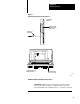
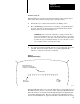
If an EPROM needs to be installed, perform the following steps to program an
EPROM and refer to Figure 4–3:
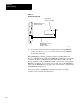
1. Turn the Processor’s Mode Select Switch to the PROG position and
connect an external battery pack to support RAM memory as shown in
Figure 4–4.
2. Remove AC power from the system.
3. Remove the Processor from the I/O Chassis. Grip a blank EPROM at its
edges and check all pins to ensure they are clean and straight. Install the
blank EPROM in the Processor as described in Section 3.5.2. Reinstall the
Processor in the I/O Chassis and restore AC power.
4. Connect one end of the Power Supply Cable (Cat. No. 1772–CA) to the
Power Supply (Cat. No. 1770–P3 or –P3A). Connect the Power Supply’s
AC power cord to a grounded AC outlet (Figure 4–3).
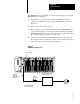
Figure 4.3
EPROM
Programming Setup
10136-I
Memory LED
Power Supply Cable
(Cat. No. 1772CA)
To Interface
Socket on
MiniPLC2/15
Processor
Molex
Connectors
25.5V DC Power Supply
(1770P3 or P3A)
To Ground
AC Outlet