Bulletin 1772 Mini-PLC-2/15 Programmable Controller Assembly and Installation Manual
Table of Contents Introduction . . . . . . . . . . . . . . . . . . . . . . . . . . . . . . . . . . . . 1 1 General . . . . . . . . . . . . . . . . . . . . . . . . . . . . . . . . . . . . . . . . . . . PC Definition . . . . . . . . . . . . . . . . . . . . . . . . . . . . . . . . . . . . . . . Fundamental Concepts . . . . . . . . . . . . . . . . . . . . . . . . . . . . . . . . Pre Assembly & Installation . . . . . . . . . . . . . . . . . . . . . . . . . . . . 1 1 1 1 1 1 1 2 Controller Components . . . .
ii Table of Contents Specifications . . . . . . . . . . . . . . . . . . . . . . . . . . . . . . . . . . 6 1 General . . . . . . . . . . . . . . . . . . . . . . . . . . . . . . . . . . . . . . . . . . . Mini-PLC-2/15 Processor . . . . . . . . . . . . . . . . . . . . . . . . . . . . . System Power Supply . . . . . . . . . . . . . . . . . . . . . . . . . . . . . . . . I/O Equipment . . . . . . . . . . . . . . . . . . . . . . . . . . . . . . . . . . . . . . Industrial Terminal . . . . . . . . . . . . . . .
Chapter 1 Introduction General The Bulletin 1772 Mini-PLC-2/15 Programmable Controller is a digital, electronic, solid state industrial programmable controller capable of monitoring and controlling up to 128 I/O devices. The Controller has a Processor, a power supply and a number of user-selected I/O Modules chosen for the number and type of I/O devices in the user’s application.
Chapter 1 Introduction The Processor stores all I/O device status data in a central read/write memory. This allows the latest status data to be accessible during the scanning of the user program.
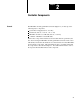
Chapter 2 Controller Components General The Mini-PLC-2/15 Programmable Controller (Figure 2.1) is made up of the following major components: System Power Supply(Cat. No. 1771-P1) I/O Chassis (Cat. No. 1771-A1, -A2 or -A4) Mini-PLC-2/15 Processor Module (Cat. No. 1772-LV) A number of Bulletin 1771 I/O Modules. Each of these components and their associated cables must be specified by the user when ordering the Mini-PLC-2/15 Programmable Controller.
Chapter 2 Controller Components Figure 2.1 Mini PLC 2/15 Programmable ControllerComponents Mini PLC 2/15 Processor (Cat. No. 1772 LV) System Power Supply (Cat. No. 1771 P1) I/O Chassis Assembly (Cat. No. 1771 A1, A2, A4) Battery Pack (Cat. No. 1771 BB) I/O Power Cable (Cat. No.
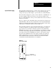
Chapter 2 Controller Components System Power Supply The System Power Supply (Cat. No. 1771-P1) is the required power source for the Mini-PLC-2/15 Controller (Figure 2.1). It converts the incoming AC voltages into the proper DC voltages to power the Processor and I/O Modules. The System Power Supply can operate on either 120V AC or 220/240V AC. It provides a regulated output of 5.1V DC to power the logic circuitry of the Processor and I/O Modules.
Chapter 2 Controller Components Battery Pack The Battery Pack (Cat. No. 1771-BB) is shipped standard with the System Power Supply and consists of: A metal Battery Housing (Cat. No. 1771-BH) A mounting Hardware Set (Cat. No. 1771-BX) Two D-size alkaline batteries (Cat. No. 1771-BA) An optional lithium battery (Cat. No. 1770-XO) can be ordered for use with the Battery Pack, is preferred.
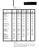
Chapter 2 Controller Components Table 1.A Module Reference Chart Cat. No. Module's Load on System Power Supply AC/DC (120V) Input DC (12 24V) Input DC (48V) Input Isolated AC/DC (120V) Input Analog (8 bit) Input Analog (12 bit) Input 1771 IA 1771 IB 1771 IC 1771 ID 1771 IE 1771 IF TTL Input DC (24 28V) Input Encoder/Counter (5V) Keying Band Positions Between Nos. Field Wiring Arm (Cat. No. 1771 ) Color Coded Label 74mA 74mA 74mA 50mA 400mA 1.
Chapter 2 Controller Components Terminal Strip AC input connections are made to the terminals on the Power Supply labeled L1 and L2. L1 is the high side of the AC line and L2 is the low side (Figure 2.2). Power Supply Indicators The two indicators on the front of the System Power Supply (Figure 2.2) are: DC ON BATTERY LOW The red DC ON indicator illuminates when the System Power Supply is operating properly; that is, the AC line voltage and DC output voltages are within their normal ranges.
Chapter 2 Controller Components Optional Power Supply Source It is permissible to use the 1771-P2 Auxiliary Power Supply in place of the 1771-P2 System Power Supply. It should be noted, however, that RAM memory will be lost if an AC power loss occurs. One of two cables is used with this power supply: 1771-CE Power Cable (1 ft/30.5 cm) 1771-CD Power Cable (5 ft/1.5 m) I/O Chassis The I/O Chassis is the compact, slotted until that houses the Mini-PLC-2/15 Processor Module and the I/O Modules.
Chapter 2 Controller Components Mini PLC 2/15 Processor The Mini-PLC-2/15 Processor Module (Cat. No. 1772-LV) is the central processing unit and memory of the programmable controller. It has 2K words of memory for the Data Table, User Program and messages. it can monitor and control up to 128 I/O devices that are wired to I/O Modules in the I/O Chassis. The Processor examines data from input devices, processes this data according to the User Program, and transmits data to control the output devices.
Chapter 2 Controller Components memory, a discrepancy in memory data, or a parity error. This indicator is normally OFF. In the PROGRAM mode this red indicator is used during EPROM programming. While EPROM programming is in progress, this indicator will blink ON and OFF. When EPROM programming has been successfully completed without error, this indicator will stay OFF. If an error in EPROM programming occurs, this indicator will come ON and stay ON.
Chapter 2 Controller Components Mode Select Switch The Mode Select Switch (Figure 2.5) places the Processor in one of four operating modes: PROG - This switch position places the Processor into the PROGRAM mode of operation. The User Program instructions are entered into memory in this switch position. EPROMs are programmed in this mode. All output devices are disabled. When a programmed EPROM is already in place, this mode is limited by the Memory Write Protect feature.
Chapter 2 Controller Components INTERFACE Socket The 15-pin socket labeled INTERFACE is used in connecting the Processor to the Industrial Terminal (Cat. No. 1770-T3) for programming, report generation or monitoring. This socket is also used to connect an external Battery Pack to the Processor so the Processor can be removed from the I/o Chassis without loss of memory. When programming an EPROM this INTERFACE socket is used to connect the 25.5V Power Supply to the Processor.
Chapter 2 Controller Components Figure 2.6 Typical Input and Output Modules (a) Output Module (b) Input Module 10841 I Field Wiring Arms Wiring to and from user I/O devices connects to a separate Field Wiring Arm for each I/O module. The Field Wiring Arm is a terminal strip that pivots up and down for quick, easy insertion and removal of I/O modules (Figure 2.7) without disturbing filed wiring.
Chapter 2 Controller Components I/O Addressing Each terminal on a Field Wiring Arm is identified by a 5-digit address (Figure 2.8). The 5 digits in the terminal address directly correspond to a memory location in the Processor’s Data Table and designate the following: The first digit is either a 0 for outputs or a 1 for inputs. The second digit refers to the Rack Number (always 1 for the Mini-PLC-2/15 System). The third digit refers to the Module Group Number (0-7).
Chapter 2 Controller Components Industrial Terminal The Industrial Terminal System (Cat. No. 1770-T3) is used to enter, monitor, edit and troubleshoot the User Program in the memory of the Mini-PLC-2/15 Processor (Figure 2.10). In addition, it can be used for report generation or to interface peripheral devices to the Processor. The 1770--T1 or -T2 Industrial Terminals can be used with the Mini-PLC-2/15 Processor, however, they will limit the capabilities of the Processor.
Chapter 2 Controller Components Figure 2.9 Module Groups 0 0 1 2 1 3 2 4 3 5 4 6 5 7 6 7 32 I/O 64 I/IO 128 I/O 10108-I Figure 2.10 Industrial Terminal (Cat. No.
Chapter 3 Assembly and Installation General Safety is a primary consideration in programmable controller installations and operations. The procedures in this section consider the safety of the operator, of the controlled equipment and of the Controller. These procedures are intended to supplement the applicable codes and ordinances that govern wiring and installation practices. Personnel installing the Controller system should become familiar with local codes as well as these procedures.
Chapter 3 Assembly and Installation EXCESSIVE HEAT For most applications, normal convection cooling keeps Controller components within the 00 to 600C ambient operating range. Thus, the proper spacing of components within the enclosure is usually sufficient for heat dissipation. There are however, some applications where a substantial amount of heat is generated by equipment either inside or outside the enclosure.
Chapter 3 Assembly and Installation Figure 3.1 Typical Suppression for Small AC Inductive Load 120V AC 1 0.5 µ f 220 Ω Discrete Component Equivalent 1 Allen–Bradley surge Suppressors: Cat. No. 1691–N2: General Purpose Cat. No. 599–K04: Bulletin 509 Starters Cat. No. 700–N5. N9 N24: 700 N Relays Cat. No. N10: Bulletin 709 Starters 10109–I Figure 3.2 Typical Suppression for 3 Phase Inductive Load Electrocube Part No. 1676–13 (3 Required) 240/480V AC CR5 CR5 CR5 0.
Chapter 3 Assembly and Installation Figure 3.3 Typical Suppression for Large AC Inductive Load 120V AC CR4 Electrocube Part No. RG1676 14 0.47 m f 220 W V130 LA1 Discrete Component Equivalent General Electric MOV (Metal Oxide Varistor) 10111 I Figure 3.4 Typical Suppression for Small DC Inductive Load + V DC PIV (Peak Inverse Voltage) rating of diode must be at least twice the applied DC voltage - 10112-I All possible sources of noise should be suppressed.
Chapter 3 Assembly and Installation CONSTANT VOLTAGE TRANSFORMER In applications where the AC line is especially unstable and subject to unusual variation, a constant voltage transformer can be used to stabilize the input voltage to the System Power Supply as well as the input voltage to the user devices. A constant voltage transformer compensates for voltage changes at its input to maintain a steady voltage at its output.
Chapter 3 Assembly and Installation Enclosure Considerations An enclosure is usually provided by the user for housing the Mini-PLC-2/15 Controller. The enclosure is the primary means of protecting the Controller from atmospheric contaminants (oil, moisture, conductive dust or particles, or any corrosive or otherwise harmful airborne substance).
Chapter 3 Assembly and Installation Rule 1 - Allow at least 6 vertical inches above and below all Controller components. when more than one Controller is mounted in an enclosure, allow at least 6 vertical inches between Controllers. Do not mount any component above a 600C air temperature level. Rule 2 - Allow at least 4 horizontal inches on the sides of each Controller component. when two or more Controllers are mounted in the same horizontal plane, allow at least 6 horizontal inches between them.
Chapter 3 Assembly and Installation General Grounding Information Grounding is an important safety measure in electrical installations. With solid state control systems, grounding has added value because it helps to reduce the effects of noise due to electromagnetic noise interference (EMI). Allen-Bradley Programmable Controller components and their enclosures must be properly grounded. All applicable Codes and Ordinances should be observed when wiring the Controller.
Chapter 3 Assembly and Installation Figure 3.6 Minimum Component Spacing Requirements (Separately Mounted Power Supply) Area reserved for Disconnect, Constant Voltage Transformer, Control Relays Motor Starters or other User Devices. ÉÉÉÉÉÉÉÉÉÉÉÉÉ ÉÉÉÉÉÉÉÉÉÉÉÉÉ ÉÉÉÉÉÉÉÉÉÉÉÉÉ ÉÉÉÉÉÉÉÉÉÉÉÉÉ ÉÉÉÉÉÉÉÉÉÉÉÉÉ ÉÉÉÉÉÉÉÉÉÉÉÉÉ ÉÉÉÉÉÉÉÉÉÉÉÉÉ ÉÉÉÉÉÉÉÉÉÉÉÉÉ ÉÉÉÉÉÉÉÉÉÉÉÉÉ 6" (15.24cm) 4" (10.16cm) 6" (15.24cm) 2" (5.08cm) 4" (10.16cm) 4" (10.16cm) 6" (15.24cm) 2" (5.
Chapter 3 Assembly and Installation Each vertical group of components is connected together (Figure 3.7) and these groups are connected to a ground bus mounted on the back panel of the enclosure (Figure 3.8 and Figure 3.9). The ground bus is connected to the grounding electrode system through a grounding electrode conductor. Avoid connecting more than two lugs to a single bolt since the compression of the metal lug can loosen the connection.
Chapter 3 Assembly and Installation Chassis Pre Assembly Before the Mini-PLC-2/15 Controller is mounted to an enclosure, the I/O Chassis must be partly assembled. This involves setting the Switch Group Assembly, installing keying bands and installing the Battery Pack. In addition, if the side mounting configuration is used, the System Power Supply should be mounted to the Chassis before the Chassis is mounted to the enclosure back panel. Figure 3.
Chapter 3 Assembly and Installation Figure 3.10 Ground Connections at Enclosure Wall Enclosure Wall (Inside) Scrape paint on both sides Bolt Star washer Ground lug Enclosure Wall (Outside) Star washer Equipment Grounding Conductor Nut 10020 Switch Group Assembly Located near the lower left side of the I/O Chassis are numbered switches in a Switch Group Assembly (Figure 3.11). Switch 1 must be set ON or OFF to determine output response to a fault.
Chapter 3 Assembly and Installation Figure 3.11 Switch Group Assembly 4 slot I/O Switch Group Assembly 10698 I Battery Pack The Mounting Hardware Set (Cat. No 1771-BX), which consists of two mounting brackets with screws, is mounted to the left side plate of the I/O Chassis (Figure 3-13). When mounted, the brackets provide tracks on which the Battery Pack slides. The two alkaline batteries are installed in the Battery Pack (Cat. No. 1771-BB) with the polarity shown in Figure 3-14.
Chapter 3 Assembly and Installation Install one lithium batter in the front battery compartment, seam side down, with the polarity shown in Figure 3-15. Reconnect the 3-pin connector at the base of the Battery Pack. When the batteries are installed, slide the Battery Pack onto the tracks and tighten the thumbscrew. Figure 3.12 Switch Group Settings O N 1 2 3 4 5 6 O F F 7 8 ON ON OFF Side View No Significance ON: Outputs remain in last state when Fault is detected.
Chapter 3 Assembly and Installation Figure 3.13 Mounting Hardware Set Brackets installed by user Battery Pack slides on tracks 10699 I Figure 3.
Chapter 3 Assembly and Installation Figure 3.15 Lithium Battery Installation + Orientation + Lithium Battery Battery Contacts 10120b I 10680 I Figure 3.16 Keying Band Installation Keying Bands Backplane Socket 2 4 6 8 10 12 14 16 18 20 22 24 26 28 30 32 34 36 10112-I Keying Bands Plastic keying bands (Cat. No. 1777-RK), shipped with each I/O Chassis, can be inserted into the top backplane sockets of the I/O Chassis (Figure 3.16).
Chapter 3 Assembly and Installation Before installing the keying bands, I/O Module placement with the I/O Chassis must be determined. A general rule of thumb is to group I/O Modules by signal type. For field wiring guidelines and considerations, refer to Section titled Field Wiring Considerations and Field Wiring Guidelines.
Chapter 3 Assembly and Installation I/O Chassis Assembly Once the Chassis and Power Supply are mounted, the remaining Controller parts can be installed in the I/O Chassis. This includes installing the I/O Power Cable, keying bands, EPROM, Processor, Field Wiring Arms and I/O Modules. Figure 3.
Chapter 3 Assembly and Installation Figure 3.18 I/O Chassis Dimensions 23.4” (59.44cm) 128 I/O 13.4” (34.04cm) 64 I/O 11.25” (28.5cm) 10.0” (25.4cm) 6.75” (17.15cm) 14.15” (35.94cm) 64 I/O 8.51” (21.62cm) 24.15” (61.34cm) 128 I/O 10124-I I/O Power Cable For ease of installation, the I/O Power Cable is installed prior to installing the Mini-PLC-2/15 Processor Module. The I/O Power Cable comes in two lengths to accommodate either Power Supply mounting configuration: 1 ft/30.5 cm (Cat. No.
Chapter 3 Assembly and Installation EPROM Installation If the optional EPROM (Cat. No. 1770-XP) is to be used for non-volatile memory, it should be installed in the Mini-PLC-2/15 Processor before the Processor is installed in the I/O Chassis. Refer to the EPROM data sheet, Publication 1770- 915, for a complete description of the EPROM. To install the EPROM, perform the following steps (Figure 3.22): 3 20 1. Grip the EPROM at the edges and check all EPROM pins to ensure they are not bent or dirty. 2.
Chapter 3 Assembly and Installation Figure 3.19 Power Supply and I/O Chassis Dimensions 1.55" (3.93cm) + + + 10.0" (25.4cm) + 7.16" (18.2cm) 8.51" (21.62cm) + + 12.71" (32.54cm) 17.71" (44.98cm) 32 I/O 64 I/O 128 I/O 27.71" (70.38cm) Note: For ease of assembly, Power Supply and I/O Chassis should be a unit before mounting.
Chapter 3 Assembly and Installation Figure 3.20 System Power Supply Dimensions 2.0” (5.0cm) + 10.0” (25.4cm) 11.25” (28.5cm) + 4.56” (11.6cm) 7.16” (18.2cm) 10126-I Figure 3.21 I/O Power Cable Thumbscrew 3 Pin Socket + + 9 Pin Socket I/O Chassis Socket I/O Power Cable (Cat. No.
Chapter 3 Assembly and Installation Figure 3.22 EPROM Installation Notch ON Lock OFF 24 Pin EPROM Release 10128 I 5. Line up the right side of the EPROM pin with the right side of the socket and seat the EPROM in the socket. 6. Lock the EPROM in place by pushing the OFF tab toward the right. 7. Close the EPROM access door ad tighten the screw. Mini PLC 2/15 Processor The Mini PLC-2/15 Processor Module (Cat. No. 1771-LV) is inserted into the left-most slot of the I/O Chassis (Figure 3.23).
Chapter 3 Assembly and Installation When a pair of I/O Modules (a Module group) is seated, the Module Locking Latch at the the top of the I/O Chassis is snapped down to secure the I/O Module (Figure 3.15). The Field Wiring Arm is then pivoted up and snapped onto the wiring arm locking tab. Figure 3.
Chapter 3 Assembly and Installation Wiring/Cabling Installation Before actually running the signal wiring, refer to the wiring guidelines as outlined under “Field Wiring Considerations” and “Field Wiring Guidelines,” Section titled Field Wiring Considerations and Field Wiring Guidelines. Wiring installation will be discussed as it related to components.
Chapter 3 Assembly and Installation Figure 3.24 Attaching Filed Wiring Arms Wiring Arm Horizontal Bar C Shaped Bracket Remove Install 10842 I Field Wiring Considerations When planning duct layout, the following categories of wires and cables associated with an A-B Programmable Controller should be considered: I/O Power Cable carries regulated 5V to the Processor and the I/O Rack. Data Highway Cables (Serial Communication) carry data transmissions between Processors and/or Computers.
Chapter 3 Assembly and Installation Figure 3.25 I/O Module Insertion Module Locking Latch Wiring Arm Locking Tab Plastic Tracks Guide I/O Modules into Position 10843 I Field Wiring Guidelines The following are general wiring guidelines for A-B Programmable Controller components. These guidelines are applicable to typical installations for user wiring inside and outside the enclosure: Use 14 AWG (stranded) wire or smaller as permitted by local codes to connect to the Field Wiring Arms.
Chapter 3 Assembly and Installation Figure 3.
Chapter 3 Assembly and Installation Figure 3.27 Field Wiring Arm/Indicator Labeling Label for Status Indicators Label for Field Wiring Arm Terminals 10844 I All Low Level DC I/O lines must be properly shielded and run in a separate duct. Serial Communication Cables may also be run with these lines. I/O Power Cable should remain external to all wiring ducts or in a duct not shared with other wiring within the enclosure.
Chapter 3 Assembly and Installation Bend the end of the wire to to the right and place the bare copper wire under the pressure plate of the terminal screw. (Optionally, a spade lug can be used.) Tighten the screw, and check that the wire is firmly in place. Bundle each Module’s wires together and push them into the wiring duct. when completed, the bundled wires should look similar to those shown in Figure 3.28.
Chapter 3 Assembly and Installation Figure 3.28 Field Wiring Arm Leave Sufficient Slack for Pivoting Figure 3.
Chapter 3 Assembly and Installation Figure 3.30 Twisting Foil Shield and Wiring White wire Twist foil and bare wire together Black wire 10708-I Figure 3.
Chapter 3 Assembly and Installation Figure 3.32 Cable Shield Connection Ground Shield at I/O Chassis Mounting Bold Shield and Drain Twisted into Single Strand Field Wiring Arm 17798 The shield cable at the field devices can be configured as described in Figure 3.33. Incoming AC Wiring Guidelines When bringing AC power into the enclosure, the raceway or conduit may be an equipment grounding conductor which should be connected to the ground bus on the back panel.
Chapter 3 Assembly and Installation When the System Power Supply Chassis cannot be directly connected to the enclosure or the enclosure ground bus, an equipment grounding conductor must be connected to the terminal labeled “Equipment Ground” on the System Power Supply’s terminal strip. Master Control Relay A hard-wired Master Control Relay, supplied by the user, provides emergency power shutdown for Controller I/O devices.
Chapter 3 Assembly and Installation WARNING: To avoid injury to personnel and damage to equipment, disconnect all AC and DC power to the Controller before attempting any wiring installation within the enclosure. Figure 3.33 Shielded Cable at User's Device Insulated wires connect to user device. Cut shield and bare drain wire short. Bend back and tape to insulated shield from contact at this end of cable.
Chapter 3 Assembly and Installation CAUTION: The user must make certain that the System Power Supply is correctly jumpered for either 120V or 220/240V AC. Incorrect jumpering on the terminal strip may cause improper operation or damage to the Power Supply.
Chapter 3 Assembly and Installation Industrial Terminal Installation The Bulletin 1770 Industrial Terminal System (Cat. No. 1770-T3) is used to program the Mini-PLC-2/15 Processor. The Industrial Terminals (Cat. No. 1770-- T1 or -T2) can be used, however they will limit the capabilities of the Mini- PLC-2/15 Processor. WARNING: Do not use a 1770-T1 or 1770-T2 Industrial Terminal to edit or change a program or Data Table values that were generated using a 177-T3 Industrial Terminal.
Chapter 3 Assembly and Installation Figure 3.
Chapter 3 Assembly and Installation Figure 3.
Chapter 3 Assembly and Installation Figure 3.36 External Power Terminal Strip L1 120V AC 220/240V AC Jumper positions indicated at side of terminal strip 120V AC L2 EQUIP GND 10132-I Figure 3.37 Industrial Terminal Connection Industrial Terminal INTERFACE Channel A Cat. No. 1772 TC (10 Feet, 3.
Chapter 4 System Start-Up Start-Up Careful start–up procedures are essential for proper Mini–PLC–215 Controller operation. These procedures should be followed after the complete Controller system has been assembled and installed as described in Section 3. A cautious approach must be taken toward the initial start–up procedure. Care and patience during start–up will isolate problems that might occur in the form of programming errors, wiring mistakes, or equipment malfunction.
Chapter 4 System Start-Up 4. Verify that the I/O Power Cable connectors are plugged securely into their sockets. 5. Verify that all modules are securely held in the I/O Chassis. Verify that the Field Wiring Arms are fully seated on their I/O Modules and locked in place on the locking tables. 6. Disconnect all motors from their starters, valves from their solenoids, etc., to ensure that no power–driven machine motion occurs when power is first applied to the Controller.
Chapter 4 System Start-Up Figure 4.1 I/O and Industrial Terminal Status Indicators Input module Indicator Module Indicator Illuminates when Device is On Input Device (On or Off) Diaplay Intensifies TRUE Instruction 110 110 112 11 12 13 Industrial Terminal (Cat. No. 1770 T3) 10134 I 10134 I Hardware/Indicator Comparison Procedures WARNING: Machine motion during this procedure can cause injury to personnel or damage to equipment.
Chapter 4 System Start-Up The user must make certain that a program has not been entered into the Mini– PLC–2/15 Processor’s memory. Only one rung at a time should be in memory for the start–up procedures. To clear the Processor’s memory, connect the Industrial Terminal to the Mini–PLC–2/15 Processor and perform the following steps. Read and understand the Industrial Terminal System User’s Manual, Publication 1770–805 before proceeding. 1.
Chapter 4 System Start-Up TESTING INPUTS Hardware/indicator comparison should begin with the testing of input devices and modules. Perform the following steps for each input device: 1. Turn the Processor’s Mode Select Switch to the TEST position. 2. Press [SEARCH][5][3] and enter the word address of the Input Module to be tested. The state of each input in the selected Module Group will be displayed in the format shown in Figure 4–2.
Chapter 4 System Start-Up CAUTION: If an I/O Module is to be replaced, System power and I/O power must be removed. Failure to remove power could result in damage to the Module and/or unexpected machine motion. Perform steps 2 and 3 until all inputs have been tested. TESTING OUTPUTS After all inputs have been tested, the outputs should be checked next. Some output devices are disconnected and must remain disconnected during this checkout procedure.
Chapter 4 System Start-Up Checkout of Machine Motion At this point, the Controller, the connections and mot of the user’s hardware will have been tested. The final procedure is to check out the machine motion or process controlled by the actual User Program. The basic approach initiates testing with the least amount of machine motion. Only some outputs are allowed to generate machine motion.
Chapter 4 System Start-Up WARNING: Never reach into a machine to actuate a switch because unexpected machine motion could occur and cause injury to personnel. Do not use a metal rod since this could result in an electrical shock if it touches and exposed terminal. Instead, use a wooden stick or other nonconductive device to activate the switch. If the output device fails to operate, check to see if the Output Module indicator is ON for the corresponding output terminal.
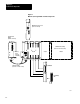
Chapter 4 System Start-Up If an EPROM needs to be installed, perform the following steps to program an EPROM and refer to Figure 4–3: 1. Turn the Processor’s Mode Select Switch to the PROG position and connect an external battery pack to support RAM memory as shown in Figure 4–4. 2. Remove AC power from the system. 3. Remove the Processor from the I/O Chassis. Grip a blank EPROM at its edges and check all pins to ensure they are clean and straight.
Chapter 4 System Start-Up Figure 4.4 External Battery Backup Battery Pack (Cat. No. 1771-BB) Mini PLC 2/15 Processor (Cat. No. 1772 LV) Mini PLC 2/15 Processor Transport Cable (Cat. No. 1772 CD) 5. 10137–I Connect the other end of the Power Supply Cable to the INTERFACE socket on the Processor. As soon as this connection is made, EPROM programming will begin. During EPROM programming, the Memory LED on the Mini–PLC–2/15 Processor will blink ON and OFF.
Chapter 5 Maintenance and Troubleshooting General The Mini–PLC–2/15 Controller has been designed to minimize the need for maintenance and troubleshooting. Status and diagnostic indicators on the Controller help to trace the source of a fault to the user’s hardware or the Controller. Preventive Maintenance The Mini–PLC–2/15 Controller is an electrical system comprised of printed circuit boards.
Chapter 5 Maintenance and Troubleshooting Generally, the sources of problems can be grouped into two board areas: User’s hardware Programmable Controller The most likely source of a problem is the user’s hardware. This includes the wiring, I/O devices, I/O power source and system power. Programmable Controller faults can originate from the System Power Supply, Mini–PLC–2/15 Processor or the I/O Rack.
Chapter 5 Maintenance and Troubleshooting Table 5.A Recommended Spare Parts Quantity Cat. No. Description POWER SUPPLY 1 1770-XO Lithium Battery or 2 1771-BA D-size Alkaline Battery 1 1771-BB Battery Pack (includes 2 alkaline batteries) 1 1771-CL I/O Power Cable (1 ft./30.5 cm) 1 1771-CM I/O Power Cable (5 ft./1.5 m) 1 1771-FP Fuse Package for Power Supply; includes 5 1A slow-blow fuses for 120V use 5 0.
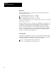
Chapter 5 Maintenance and Troubleshooting 1. Remove AC power from the System Power Supply using the main disconnect. 2. Remove the fuse cap by pushing in slightly and turning counterclockwise. The fuse cap and the fuse holder will pop out of the fuseholder. 3. Install the replacement fuse (1 amp for 120V AC; 0.5 amp for 220/240V AC) in the cap and insert into the fuse holder. Push in and turn the fuse cap clockwise to seat in the fuseholder. 4. Restore system power.
Chapter 5 Maintenance and Troubleshooting Figure 5.
Chapter 5 Maintenance and Troubleshooting A 1 WARNING: REMOVE SYSTEM POWER BEFORE CHECKING FUSE IS POWER SUPPLY FUSE BLOWN ? Yes CHECK POSITION OF JUMPERS ON POWER SUPPLY TERMINAL STRIP 1 REPLACE FUSE RESTART CONTROLLER AND VERIFY PROPER OPERATION No IS CORRECT LINE–VOLTAGE AT SUPPLY INPUTS ? No CORRECT LINE–VOLTAGE PROBLEM Yes CYCLE LINE POWER TO SYSTEM POWER SUPPLY IS DC ON INDICATOR ON ? No Yes REDUCE POWER SUPPLY LOAD TO 6.
Chapter 5 Maintenance and Troubleshooting B CONNECT INDUSTRIAL TERMINAL TO PROCESSOR AND TURN POWER ON PROCESSOR FAULT OR RUN– TIME ERROR WILL BE DISPLAYED. NO IF MODE SELECT SWITCH IS IN RUN/PROG, INDUSTRIAL TERMINAL PLACES THE PROCESSOR IN REMOTE PROG. IF IN RUN POSITION, TURN KEYSWITCH TO PROG POSITION. INDUSTRIAL TERMINAL DISPLAYS RUNG WHERE ERROR OCCURED, AND DESCRIBES ERROR. CORRECT THE RUN–TIME ERROR.
Chapter 5 Maintenance and Troubleshooting C CYCLE LINE POWER TO SYSTEM POWER SUPPLY. IS PROCESSOR INDICATOR ON ? NO RESTART CONTROLLER. VERIFY PROPER OPERATION. YES REPLACE MINI–PLC–2/15 PROCESSOR. RELOAD PROGRAM AND VERIFY PROPER OPERATION. 10141–I 2. Remove AC power from the Power Supply using the main disconnect. 3. Remove the I/O Power Cable from the Power Supply socket. To do this, squeeze in on the side levers of the cable. 4.
Chapter 5 Maintenance and Troubleshooting System Power Supply Replacement The System Power Supply should be replaced if it is unable to provide the correct output voltages to power the Processor and I/O Modules. perform the following steps to replace the Power Supply: 1. Turn the Processor’s Mode Select Switch to the PROG mode and support Processor memory.
Chapter 5 Maintenance and Troubleshooting Table 5.B Troubleshooting Chart Controller Mode[1] Troubleshooting Indicators Processor Memory Run DC ON ON OFF OFF ON 1. Cycle line power. 2. Replace Processor T, R, or R/P OFF OFF OFF OFF 1. 2. 3. 4. T or R ON ON OFF ON 1. Connect Industrial Terminal to Processor and turn Mode Select Switch to PROG. 2. If a run-time error occurred, correct it. 3. If a Processor fault occurred, turn keyswitch back to TEST or RUN. 4.
Chapter 5 Maintenance and Troubleshooting Figure 5.2 Power Supply/Power Cable Outputs Pin No. 7 8 9 7 8 9 4 5 6 4 5 6 1 2 3 1 2 3 12 Logic Voltage, +5.1V DC + – 3% 3 Chassis Ground 4.5 I/O Power Cable End 1 Common 6 Battery Fail (Low-True) 7 Battery (+) (2.7-3.7V DC) 8 Memory Voltage +5V DC + – 5% Processor Enable (Low-True) 9 System Power Supply Socket Function 1 Battery Voltage at Pin No. 7 is not measurable at base of Power Supply. 10143-I Mini-PLC-2/15 Processor 2.
Chapter 5 Maintenance and Troubleshooting nature of the problem. The possible combinations of indicator status are summarized in Table 5.B. Processor Faults and Run-Time Errors Any time the PROCESSOR indicator goes ON by itself during operation, this indicates that a hardware fault in the Processor has occurred. The only way to correct this type of fault is by cycling line power using the main disconnect or by replacing the Processor.
Chapter 5 Maintenance and Troubleshooting CAUTION: When removing the Mini–PLC–2/15 Processor from the I/O Chassis, always remove system power and I/O power first. This will avoid damage to the Processor Module’s circuitry. 1. Turn Mode Select Switch to the PROG position. 2. Connect an external battery pack to the Processor (Figure 4–4). 3. Remove AC power and I/O power. 4. Remove the Processor from the I/O Chassis and remove the EPROM. 5.
Chapter 5 Maintenance and Troubleshooting 4. Remove the Processor from the I/O Chassis. 5. Remove the EPROM if installed in the Processor and install it in the replacement Processor if necessary. 6. Install the replacement Processor in the I/O Chassis and turn the Mode Select Switch to the PROG position. 7. Restore AC power and I/O power. 8. Load the User Program and verify proper operation. If an EPROM is used, it will transfer its content into RAM memory when power is restored.
Chapter 5 Maintenance and Troubleshooting Output Module Fuse Replacement If the FUSE BLOWN indicator on any of the Output Modules is illuminated, one or more Output Module fuses is blown. Perform the following steps to replace a blown Output Module fuse: CAUTION: Replacement fuses must be the correct type and rating. using the wrong fuse can result in damage to equipment or Module circuitry. WARNING: Contact with AC line potentials may cause injury to personnel.
Chapter 5 Maintenance and Troubleshooting I/O Module Replacement If the I/O Module is the suspected source of the fault, it should be replace with the identical type and compatible series Module. Perform the following steps to replace the I/O Module: WARNING: Contact with AC line potentials may cause injury to personnel. Removing power from the System Power Supply does not remove the external power source supplying the Field Wiring Arm.
Chapter 5 Maintenance and Troubleshooting Figure 5.3 Removing Fuse Access Cover CAT. NO. 1771 OC (48V) DC OUTPUT MODULE ALLEN BRADLEY CO. SYSTEM DIVISION CLEVELAND, OHIO Remove these 2 Front Screws to remove Cover over Fuses. (Cover on reverse side) 10705 I Figure 5.
Chapter 6 Specifications General This section contains physical, electrical and functional information on each Mini–PLC–2/15 Controller component.
Chapter 6 Specification System Power Supply Input Voltage Range 98-132V AC (120V AC operation) 196-250V AC (220/240V AC operation) Frequency Range 50/60 Hz (47-63 Hz) Output Voltage +5.1V DC (logic circuitry) +5V DC (memory) Maximum Output Current 6.5 amps Input Power 75 VA (approx.) Power Capability One Mini-PLC-2/15 Processor and One 1771 I/O Rack (128 I/O Location Side plate of Bulletin 1771 I/O Chassisor up to 5 cable-feet above I/O Chassis Battery Type 2 Alkaline D-size 1.5V or Lithium D-size 3.
Chapter 6 Specification I/O Equipment The following are summary specifications for Bulletin 1771 I/O Chassis. For specifications on individual I/O modules, refer to the product data sheets. Chassis Dimensions (WxHxD) Inches 32 I/O: 9.15 x 11.25 x 6.75 64 I/O: 14.15 x 11.25 x 6.75 128 I/O: 24.15 x 11.25 x 6.75 Centimeters 32 I/O: 23.24 x 28.58 x 17.15 64 I/O: 35.94 x 28.58 x 17.15 128 I/O: 61.32 x 28.58 x 17.15 Chassis Sizes 32 I/O, Cat. No. 1771-A1, contains 4 I/O slots (2 Modules Groups) 64 I/O, Cat. No.
Index Symbols **Empty**, 5 1, 5 4 A AC Input Fuse, 2 5 Wiring, 3 33 Access, EPROM, 2 11 Address, Five Digit, 2 14 Addressing, I/O, 2 13 Alkaline Battery, 3 15 Assembly Chassis, 3 11 I/O Chassis, 3 11 Switch Group, 3 12 Attaching Field Wiring Arm, 3 26 B Background, 1 2 Battery Pack Description, 2 4 Installation, 3 13 C Cable Power, I/O, 2 4, 3 22 Shield Connection, 3 33 Chart Module, 2 5 Troubleshooting, 5 10 Chassis, Mounting, 3 17 Chassis, Assembly, 3 11 Checkout Final, 4 7 Machine motion, 4 7 Power u
I–2 Index G Ground Component, 3 8 Enclosure, 3 6 General, 3 8 I I/O Chassi, Pre-Assembly, 3 11 Chassis, Assembly, 3 18 Chassis, Sizes, 2 8 Module, Description, 2 11 Module, Installation, 3 20 Module, Replacement, 5 16 Module, Typical, 2 12 Power Cable, 2 4 Wiring, 3 23 I/O Power cable, 3 19 Industrial Terminal Description, 2 14 Status Indicators, 4 2 Installation, 1 2 Battery Pack, 3 13 EPROM, 3 20 I/O Power Cable, 2 4 Keying bands, 3 16 Processor, 3 23 Recommendations, 3 1 K Keying Bands, 3 16 M O Op
Index Troubleshooting General, 5 1 Power Supply, 5 2 Processor, 5 11 U User Supplied Equipment, 2 14 I–3 V Voltage Measurement, Power Supply, 5 4
Allen Bradley has been helping its customers improve productivity and quality for 90 years. A B designs, manufactures and supports a broad range of control and automation products worldwide. They include logic processors, power and motion control devices, man machine interfaces and sensors. Allen Bradley is a subsidiary of Rockwell International, one of the world's leading technology companies. With major offices worldwide.