
Instruction Manual


Hardware
Chapter 3
3-5
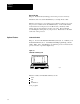
Fuse
Purpose: Guards against overcurrent conditions on the input line.
Sizes: 1.0 amp fuse for 120V AC operations
Terminal Strip
Purpose: To provide wire connections for the processor.
Hardware: Terminals L1, N and GND label the AC input connections.
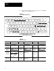
Switch
Assembly on the I/O Chassis
Purpose: Determines processor response to memory protect and
power-up sequence.
Location: Left side of the I/O chassis backplane.
Settings:
If Then
Switch 8 is on Memory protection is on. Memory above 20
08
cannot be changed by
the programmer.
Switch 8 is off Memory protection is disabled. memory can be changed by the
programmer. Memory can be changed when the processor module is
in the program mode.
Switch 6 is off Contents of the EEPROM is always transferred to the CMOS RAM at
powerup.
Switch 6 is on
and
Switch 7 is off
Memory transfer does not occur and the module gives a fault
indication.
Switch 6 is on
and
Switch 7 is on
If the CMOS RAM passes its checksum on powerup, the contents of
the EEPROM transfer to the CMOS RAM.
The settings for Switch 1- Switch 5 do not matter.
Important: Series A/Revision A of the 1770-T3 industrial terminal is not
compatible with memory protect feature.
ATTENTION: Use a ball point pen to set each switch. Do not
use a lead pencil because the tip can break off and jam
the switch.