
Instruction Manual


Hardware
Chapter 3
3-3
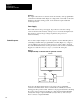
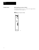
Processor
Status Indicator
PROC RUN/FAULT: This red/green LED keeps you informed of the
processor’s operating conditions.
Table 3.A
Status
Indication
Status
Indicator
If the
color is
Then the Indication represents
PROC RUN/FAULT Green
Blinking Green
Red
Off
The processor module is in the run mode and will
begin operation.
The EEPROM memory module (if present) is being
programmed.
There is a fault. Recycle power to reset the
processor module.
Either program mode of operation, run time error,
memory error or a program error.
P/S ACTIVE Green
Off
AC and DC is all right.
There has been a power supply fault, overcurrent
condition, improper input voltage or the module has
been turned off.
MEMORY STORE (Switch)
Purpose: Enables you to backup or copy the program into the optional
EEPROM Memory Module.
Hardware: An optional EEPROM Memory Module (cat. no. 1772-MJ) can
be installed in the module.
INTFC
(Interface socket)
Purpose: The 15 pin socket, labeled INTFC, provides communication
between the processor and the programming terminal (1770-T3 or
1784-T50), the 1770-RG report generation module, the 1770-T11 hand
held terminal, the 1772-KG interface module or 1771-KA communications
interface module.
Processor Module and: Through: Catalog Number:
Industrial Terminal (cat. no. 1770T3) PLC2 Program Panel
Interconnect Cable
1772TC
Industrial Terminal (cat. no. 1784T50) PLC2 Program Panel
Interconnect Cable
1772TC or 1784CP2
Data Highway Communication Modules Data Highway/Processor Cables 1771CN, CO, or CR
PLC2 Family Report Generation Module
(cat. no. 1770RG)
PLC2 Program Panel
Interconnect Cable
1772TC
(with external ground wire only)
The 1784-T50 also requires PLC-2 6200 programming software (cat. nos.
6201-PLC2, 6203-PLC2, 6211-PLC2, or 6213-PLC2).
Function: Provides interface to the above devices.